Table of Contents
Advertisement
Quick Links
1.1.1
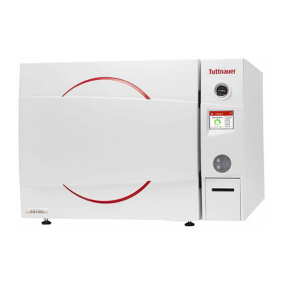
Operation and
Maintenance Manual
Electronic Laboratory Autoclaves
Models 3840, 3850, 3870 EL-D
EL-D: standard autoclave
C: optional system for fast cooling
PV: optional vacuum pump
BH: optional bio hazard filtration
F: optional fan for super-fast cooling
Cat. No. MAN205-0466001EN Rev M
Tuttnauer Europe B.V.,
Hoeksteen 11 4815 PR P.O. Box 7191 4800 GD Breda,
The Netherlands Tel: 31 (0) 765423510, Fax: 31 (0) 765423540
Advertisement
Table of Contents


Need help?
Do you have a question about the 3840 EL-D and is the answer not in the manual?
Questions and answers