Table of Contents
Advertisement
Advertisement
Table of Contents

Related Manuals for Tuttnauer E Series


Summary of Contents for Tuttnauer E Series
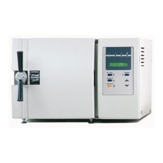
- Page 1 E-type Electronic Table -Top Autoclaves models 1730, 2340, 2540, 3140, 3850, 3870 E, EK, EA & EKA Cat. No. MAN205-0064000EN Rev. H Tuttnauer Europe b.v., Paardeweide 36, 4824 EH, Breda, P.O. Box 7191, 4800 GD Breda, Netherlands. +31/76-5423510, Fax: +31/76-5423540...
-
Page 3: Table Of Contents
TABLE OF CONTENTS PARAGRAPH PAGE NO. INTRODUCTION ....................4 SYMBOL DESCRIPTION ................. 4 TESTS ........................ 5 Installation Tests ..................5 Periodical Tests..................5 WATER QUALITY .................... 6 4.1. Water quality................... 6 4.2. Reverse Osmosis ..................6 DESCRIPTION OF THE CONTROL SYSTEM..........7 Digital Board DIG - T2................ - Page 4 9.18 Replacing the circuit breaker ............... 40 9.19 Fuses and Circuit Breaker Data............41 9.20 Replacing the water pump ..............42 9.21 Replacement of the Door Cover............43 9.22 Replacing the Locking Device .............. 44 9.23 Validation....................45 9.24 Emergency Door Opening ..............46 IN-OUT TEST....................
- Page 5 TABLE OF CONTENT (cont.) DRAWINGS PAGE NO. Control System Block-Diagram................... 7 DIG- T2 Board ......................8 ANL - T2 Board......................9 AC-T1 Board ......................10 Front View......................... 76 Vessel Assembly......................78 Door Tightening Bolt – Assembly ................79 Outer Cabinet - Assembly..................80 Water Outlet Strainer ....................
-
Page 6: Introduction
INTRODUCTION This manual, together with the operator’s manual, forms the complete edition of the Operation and Maintenance instructions. This manual is intended for the use of the technician. It is forbidden for unqualified and unauthorized personnel to service the autoclave in accordance with the instructions in this manual. Any unauthorized service may result in the invalidation of the manufacturer’s guarantee. -
Page 7: Tests
TESTS Installation Tests The service technician shall perform the following preliminary checks before operating the autoclave: Integrity Check Perform a visual check to verify that there are no dents, scratches, broken gauges, etc. Leveling Check Check that the autoclave is leveled. Leakage current test Check the precise operation of the earth leakage relay. -
Page 8: Water Quality
WATER QUALITY 4.1. Water quality The distilled or mineral – free water supplied to the sterlizer shall be according to the table below: Physical Characteristics and Maximum acceptable contaminants levels in water or steam for sterilizers (According to EN 285:2006). Evaporate residue ≤... -
Page 9: Description Of The Control System
DESCRIPTION OF THE CONTROL SYSTEM. (See CDR Control diagram). The control system is based on 3 electronic boards designed according to the autoclave requirements, the digital board DIG-T2 containing the micro- controller memories, buffers and digital ICs and the analog board ANL-T2 which performs the processing of signals coming from the sensors and switches. -
Page 10: Dig- T2 Board
— The board contains an optimal Real Time Clock (U12), which serves as a clock to the system, including a back-up battery, which ensures the clock, runs continuously even when the autoclave is not powered. This component is optimal because it is related to the operation of the printer, which is also an optional item. -
Page 11: Analog Board Anl-T2
Analog Board ANL-T2 The analog board contains the drivers of the valves, heaters and pump. It contains the sensors circuits connected to the control system, and serves as a junction to the autoclave connections. The input is 12VDC & 5VDC and the output is for all the signals to the autoclave. -
Page 12: Ac - Board - Ac-T1
AC - Board - AC-T1 This board receives command signals from ANL-T2 board designated to activate AC devices. It converts them to AC mode. The AC-T1 board provides AC filtering for the power supply to the control system and protection from sharp current fluctuations. The AC-T1 board includes: —... -
Page 13: Calibration Of Temperature And Pressure
CALIBRATION OF TEMPERATURE AND PRESSURE Method of Calibration: The calibration of temperature and pressure is performed digitally. The temperature and pressure measuring circuits are designed with components having 1% accuracy. The temperature circuit is linear and has an output of 100mV÷2400mV for a temperature range 20°C÷150°C. -
Page 14: Temperature Calibration Procedure
Temperature Calibration Procedure — Press the PROGRAM key. — The system enables to set the system’s date the time. — This operation is skipped by pressing PROGRAM key six times. — CODE: ∅∅∅ will be displayed. — Select Technician Code (011) by the UP/DN keys and press the PROGRAM key. - Page 15 Remarks: — When cursor is set under any figure, pressing the START/STOP key stops calibration. — When the cursor is set under any figure, it enables to feed this value to the reading of temperature by pressing the PARAMETERS key. Example: If the cursor is set under R68.0 on the upper row and the actual temperature of the autoclave is now 66.0ºC, by pressing the...
-
Page 16: Pressure Calibration Procedure
Pressure Calibration Procedure To perform the pressure calibration two points have to be defined allowing the calculation of new OFFSET and GAIN values. — Press the PROGRAM key. — Skip date and the time setting by pressing the PROGRAM six times. —... -
Page 17: Test Points
TEST POINTS The test point list provides testing points on the junctions on board to assist in locating the malfunction. NU TP FUNCTION VALVE +5V DC +12V DC OUT - HEATERS ‘0’V-Off 5V-On OUT-AIR-VALVE 0V-Off 5V-On OUT-EXH-VALVE... -
Page 18: Software Programming Procedures
SOFTWARE PROGRAMMING PROCEDURES General The software for the control system of E-Type autoclaves is AS FOLLWS: EaEn3WP20 for standard autoclaves. EaEn3WP20AR for autoclaves designed to operate at high altitude (above 2500 m. The software contains a table of parameters of which part of them defines the autoclave, and part defines the processes in the autoclave. - Page 19 8.2.3 Heat Standby – Heating elements operation in Standby Mode Access Code – Resolution – Value – 0 or 1 — If Heat Standby = 0, the heating elements will not operate in the Standby Mode. — If Heat Standby = 1, the heating elements will operate in the Standby mode, in a shoot mode of 1 second on, 59 seconds off.
- Page 20 8.2.7 End Temp - The ending temperature of the process If at the end of the process the temperature is higher than this temperature, the process will not end and the door will remain closed. Entry Code – 11 Resolution –...
- Page 21 8.2.10 Water Time – Time for entering water to the autoclave This value defines the entry time of the water to the autoclave to locate the electrode touching the water. This time will change from process to process and even for different autoclaves.
-
Page 22: Resetting The Autoclave
8.2.13 Req Prs+ This defines the required addition to the sterilization pressure in kpa. For example, for a sterilization temperature of 121ºC the required pressure is 204kpa. Since the system controls the sterilization process according to pressure and temperature, if Req Prs+ equals Ø, the system will maintain the pressure at 204kpa. -
Page 23: Replacement Of Components
REPLACEMENT OF COMPONENTS Safety Tests after Repair ATTENTION! After every repair or dismantling the enclosure, the autoclave should pass two safety electrical test by the Service Engineer. The following shall be performed: 1. Enclosure Leakage Current Test. Every autoclave should pass this test as follows: 1. -
Page 24: Dismantling The Outer Covers Of The Autoclave
Dismantling the Outer Covers of the Autoclave Caution! Before starting, disconnect the instrument from the power source and ensure that there is no pressure in the autoclave. Allow the autoclave to cool before removing outer covers. 1. Remove the screws holding the rear cover (1). 2. -
Page 25: Replacing The Safety Valve
Replacing the Safety Valve Caution! Before starting, be sure that the electric cord is disconnected and that there is no pressure in the autoclave. Note: These instructions are valid for both, PED and ASME type safety valves. 1. Remove the autoclave cover (see para. 9.2 “Dismantling the Outer Covers of the Autoclave”). -
Page 26: Replacing The Air Jet
Replacing the Air Jet Caution! Before starting, be sure that the electric cord is disconnected and that there is no pressure in the autoclave. 1. Remove the autoclave cover (see para. 9.2 “Dismantling the Outer Covers of the Autoclave”). 2. Remove the water reservoir cover. 3. -
Page 27: Replacing The Air Relief-Safety Relief Valve Block
Replacing the Air Relief-safety relief Valve block Caution! Before starting, be sure that the electric cord is disconnected and that there is no pressure in the autoclave. In case the water reservoir is deeply contaminated (soil, lime stone. etc.) it is recommended to replace the entire unit. 1. -
Page 28: Replacing The Electronics Board (Control Panel)
Replacing the electronics board (control panel) Caution! Make sure that the power cord is disconnected! If the electronic box was damaged by any liquid that entered the box, do not attempt to replace it. In this case only the factory technicians may repair the autoclave. - Page 29 Electronic box: 1730 Electronic box: 2340/2540...
- Page 30 Electronic box: 3140/3850/3870...
-
Page 31: Replacing Heating Elements
Replacing Heating elements Caution: Before starting, be sure that the electric cord is disconnected from the power source and that there is no pressure in the autoclave chamber. 1. Remove the autoclave cover (see para. 9.2 “Dismantling the Outer Covers of the Autoclave”). 2. -
Page 32: Replacing The Temperature Safety Thermostat
Replacing the Temperature Safety Thermostat The autoclave is supplied with a temperature thermostat, which protects the heaters and autoclave against overheating, during the dry cycle. This device reconnects automatically when the chamber cools down. Caution Before starting, disconnect the instrument from the power source and ensure that there is no pressure in the autoclave. -
Page 33: Replacing The Cut-Off Thermostat
9.10 Replacing the Cut-Off Thermostat This thermostat cuts out power to the autoclave, in the event that all other safety means do not function. For example: If the safety thermostat is defective and the temperature continues to rise, then the cut-off thermostat cuts out the power to the autoclave. -
Page 34: Cleaning And Replacing The Water Level Electrodes
9.11 Cleaning and Replacing the Water Level Electrodes The water level electrode is located at the rear bottom area of the chamber. 9.11.1 Replacing Caution Before starting, disconnect the instrument from the power source and ensure that there is no pressure in the autoclave. Allow the autoclave to cool before removing outer covers. -
Page 35: Replacing The Drain Valve
9.12 Replacing the Drain Valve Caution! Before starting, disconnect the instrument from the power source and ensure that there is no pressure in the autoclave. Allow the autoclave to cool before removing outer covers. 1. Remove the autoclave cover (see para. 9.2 “Dismantling the Outer Covers of the Autoclave”). -
Page 36: Replacing The Pressure Gauge
9.13 Replacing the Pressure Gauge Caution! Before starting, disconnect the instrument from the power source and ensure that there is no pressure in the autoclave. 9.13.1 Models 2340, 2540 Remove the door cover (see para. 9.20 “Dismantling the Autoclave’s Door Cover”). Remove the pressure gauge from the door. -
Page 37: Replacing The Locking Solenoid
9.14 Replacing the Locking Solenoid Caution! Before starting, disconnect the instrument from the power source and ensure that there is no pressure in the autoclave. 1. Remove the door cover. 2. Disconnect the wires from the connector. 3. Unscrew tightening (cat. -
Page 38: Replacing The Printer
9.15 Replacing the Printer 9.15.1 DPU20 Printer Caution! Before starting, disconnect the instrument from the power source. 1. Remove the autoclave cover (see para. 9.2 “Dismantling the Outer Covers of the Autoclave”). 2. Disconnect the connector of the flat cable (1) connecting the electronic box to the printer (2). - Page 39 9.15.2 DPU30 Printer Caution! Before starting, disconnect the instrument from the power source. 1. Remove the autoclave cover (see para. 9.2 “Dismantling the Outer Covers of the Autoclave”). 2. Disconnect the connector of the cable (1) connecting the electronic box to the printer (2). 3.
-
Page 40: Replacing The Door Switch
9.16 Replacing the Door Switch Caution! Before starting, disconnect the instrument from the power source and ensure that there is no pressure in the autoclave. Allow the autoclave to cool before removing outer covers. 1. Take off the autoclave cover (see para. 9.2 “Dismantling the Outer Covers of the Autoclave "). -
Page 41: Cleaning Water Inlet Strainer
9.17 Cleaning water inlet strainer Caution! Before proceeding, make sure that the electric cord is disconnected and there is no pressure in the autoclave. 1. Remove the cover of the autoclave. 2. Drain the water from the water reservoir. 3. Remove the water filter from the silicon tube. 4. -
Page 42: Replacing The Circuit Breaker
9.18 Replacing the circuit breaker Caution! Before starting, disconnect the instrument from the power source. 1. Remove the autoclave cover (see para. 9.2 “Dismantling the Outer Covers of the Autoclave”). 2. Disconnect the wires from the circuit breaker. 3. Remove the four screws connecting the circuit breaker to the panel (1). -
Page 43: Fuses And Circuit Breaker Data
9.19 Fuses and Circuit Breaker Data AUTOCLAVE TYPE DESCRIPTION 120V 230V 120V 230V 120V 230V 120V 230V 1730 Circuit breaker (A) Air pump fuse (A) ... -
Page 44: Replacing The Water Pump
9.20 Replacing the water pump Caution! Before starting, disconnect the instrument from the power source. 1. Remove the autoclave cover (see para. 9.2 “Dismantling the Outer Covers of the Autoclave”). 2. Disconnect the wires from the pump 3. Empty the water reservoir. 4. -
Page 45: Replacement Of The Door Cover
9.21 Replacement of the Door Cover Caution: Before starting, be sure that the electric cord is disconnected from the power source and that there is no pressure in the autoclave chamber. 1. Unscrew the four screws attaching the door cover and remove the door cover. -
Page 46: Replacing The Locking Device
9.22 Replacing the Locking Device Caution: Before starting, verify that there is no pressure in the autoclave chamber. 1. Remove the security ring (9) using a special tool. 2. Remove pin (6). 3. Remove locking device. Take care not to lose the Teflon disk (10). 4. -
Page 47: Validation
9.23 Validation Caution! Before starting the preparations for the validation, disconnect the instrument from the power source and ensure that there is no pressure in the autoclave. The validation port is located on the autoclave's door, behind a plastic plug inserted in the door cover. 1. -
Page 48: Emergency Door Opening
9.24 Emergency Door Opening Caution! Before starting, disconnect the instrument from the power source and ensure that there is no pressure in the autoclave. In order to facilitate the initial installation, the door locking position is taped in this retracted position at the factory. On completion of all installation activities this tape must be removed. -
Page 49: In-Out Test
IN-OUT TEST Before performing any trouble shooting on the autoclave, perform an “in-out test”. In this test the technician tests all the components of the system as follows: 1. Turn on the autoclave and immediately press the Up button until “IN-OUT TEST”... -
Page 50: Troubleshooting
TROUBLESHOOTING 11.1 Displayed Messages and Reference to Trouble Shooting Message Refer to trouble shooting section Para. 11.2 Para. 11.3.1Para. 11.3.2 11.4 11.5 Low Temp. 23, 28 Low Heat 4, 5, 18, 24 1, 5, 13, 14, High Temp. 1 2, 5 24, 28, 29 5, 13, 14, Low Pres. -
Page 73: List Of Spare Parts
LIST OF SPARE PARTS Cat. No. Description 1730 2340 2540 3140 3850 3870 DPU 20 THE002-0005 THE002-0005 Printer DPU 30 THE002-0022 THE002-0022 THE002-0022 DPU 20 THE002-0003 THE002-0003 Printer paper roll DPU 30 ... - Page 74 Cat. No. Description 1730 2340 2540 3140 3850 3870 Fuseholder, mini ELE035-0002 ELE035-0002 ELE035-0002 ELE035-0002 ELE035-0002 1/4 x 32 Fuse, 1/4x32, 1.25A ELE035-0055 ELE035-0055 ELE035-0055 ELE035-0055 ELE035-0055 (slow blow) Main power switch ELE035-0012 ELE035-0012 ELE035-0012 ELE035-0012 ELE035-0012 ELE035-0012 Electrode - water CMT196-0004 CMT196-0004 CMT196-0004 CMT196-0004 CMT196-0004 CMT196-0004 level, assembly...
- Page 75 Cat. No. Description 1730 2340 2540 3140 3850 3870 Control system for E CTP200-0050 CTP200-0051 CTP200-0051 CTP200-0072 CTP200-0076 CTP200-0038 models Control system for EA CTP200-0052 CTP200-0052 CTP200-0054 CTP200-0076 & EKA models Outer cover for E,EK COV173-0002 COV240-0002 COV240-0002 COV314-0002 COV385-0002 COV387-0002 Outer cover for ...
- Page 76 Cat. No. Description 1730 2340 2540 3140 3850 3870 Door safety solenoid SOL027-0002 SOL027-0002 SOL027-0002 SOL027-0001 SOL027-0001 SOL027-0001 Locking pin CMT201-0004 CMT201-0004 CMT201-0004 CMV100-0001 CMV100-0001 CMV100-0001 Spring for solenoid SPR177-0004 SPR177-0004 SPR177-0004 SPR177-0017 SPR177-0017 SPR177-0017 Tightening nut CMT201-0005 CMT201-0005 CMT201-0005 CMV10-0002 CMV10-0002 CMV10-0002 Okolon disc LOK240-0017 LOK240-0017 LOK240-0017 LOK387-0017 LOK387-0017 LOK387-0017 Door tightening bolt –...
- Page 77 Cat. No. Description 1730 2340 2540 3140 3850 3870 Rubber shock absorber SKR203-0006 SKR203-0006 SKR203-0006 SKR203-0006 SKR203-0006 for Ulka Screw BOL191-0140 BOL191-0140 BOL194-0342 BOL194-0342 BOL194-0342 NUT192-0191 NUT192-0191 NUT192-0155 NUT192-0155 NUT192-0155 Washer NUT193-0347 NUT193-0347 NUT193-0276 NUT193-0276 NUT193-0276 Rivet, Dome Head, ...
-
Page 78: Front View
FRONT VIEW Model 1730 Model 2340/2540... - Page 79 FRONT VIEW (Continue) Models 3140/3850/3870 Description 1730 2340/2540 3140 3850/3870 Reservoir water drain valve VLV170-0066 VLV170-0066 VLV170-0066 VLV170-0066 Ring for drain valve CMT240-0003 CMT240-0003 CMT240-0003 CMT240-0003 Door closing device LOK240-0001 LOK240-0001 LOK387-0032 LOK387-0032 Door switch ELE036-0009 ELE036-0009 ELE036-0009 ELE036-0009 Autoclave cover See “Outer cabinet assembly”...
-
Page 80: Vessel Assembly
VESSEL ASSEMBLY... -
Page 81: Door Tightening Bolt - Assembly
DOOR TIGHTENING BOLT – ASSEMBLY Cat. No. Description 1730, 2340, 2540 3140, 3850, 3870 Bushing LOK240-0003 LOK387-0003 Door tightening bolt assembly LOK240-0029 LOK387-0029 Locking screw housing LOK240-0005 LOK387-0005 Locking base LOK240-0012 LOK387-0012 Locking housing axe - assembly LOK240-0013 LOK387-0036 Door locking device pin LOK240-0035 LOK387-0016 Bakelite handle... -
Page 82: Outer Cabinet - Assembly
OUTER CABINET - ASSEMBLY... -
Page 83: Water Outlet Strainer
WATER OUTLET STRAINER Strainer Strainer Gasket element Housing Description Cat. No. Cap for ¼” strainer FIL175-0027 Strainer element FIL175-0046 Teflon gasket 4 mm GAS082-0008 Strainer Housing + Cap FIL175-0051... -
Page 84: Pressure Vs Temperature For Saturated Steam
PRESSURE VS TEMPERATURE FOR SATURATED STEAM psia InHg °F °C psia psig °F °C 2.95 114.5 0.10 45.8 17.1 219.7 1.18 117.9 104.3 4.44 129.3 0.15 54.1 17.2 219.9 1.18 118.6 104.4 5.90 140.2 0.20 60.1 17.2 220.1 1.19 118.6 104.5 7.39 149.1... - Page 85 psia psig °F °C psia psig °F °C 20.5 229.3 1.41 141.4 109.6 24.6 239.2 1.70 169.7 115.1 20.6 229.5 1.42 142.0 109.7 24.7 10.0 239.4 1.70 170.2 115.2 20.6 229.6 1.42 142.4 109.8 24.7 10.0 239.5 1.71 170.8 115.3 20.7 229.8 1.43...
- Page 86 psia psig °F °C psia psig °F °C 29.4 14.7 249.1 2.02 202.4 120.6 34.6 19.9 258.6 2.39 238.7 125.9 29.5 14.8 249.3 2.03 203.1 120.7 34.7 20.0 258.8 2.39 239.4 126.0 29.5 14.8 249.4 2.04 203.7 120.8 34.8 20.1 259.0 2.40 240.2...
- Page 87 psia psig °F °C psia psig °F °C 40.6 25.9 268.2 2.80 280.0 131.2 45.7 31.2 275.4 3.15 315.0 135.2 40.7 26.0 268.3 2.81 280.9 131.3 45.8 31.3 275.5 3.16 315.9 135.3 40.9 26.2 268.5 2.82 281.7 131.4 45.9 31.5 275.7 3.17 316.8...
-
Page 88: Xpcs Manual
XPCS Manual Definitions PC – Personal computer. Program – a complete, self-contained set of computer instructions that you use to perform a specific task such as word processing, accounting or data management. Program is also called Application. PCS – Cat Technologies LTD. code development, controlling and communication technology. - Page 89 Installation ♦ Select the CD drive by double click on him. ♦ When the window open find and double click on the file "setup.exe" ♦ This will launch the installer, follow the on screen instructions. Using XPCS Configuring the program On 'XPCS' main window, press on 'Options' button.
- Page 90 Modem Configurations To connect to remote target via a modem, select 'Active' check box in 'Modem Config' frame. 'Connection Timeout' it is a waiting time in seconds to requested data form the PCS target platform. If no data retrieved from the target after wait time, the program generates a communication time error.
- Page 91 By pressing on 'Connect' button, program will try to connect to remote PCS Target. Opening connection between remote PCS Target and PC, performing next tasks: ♦ Check If COM Port is available. ♦ Detect modem. ♦ Dial a phone number. ♦...
- Page 92 Calibration window The calibration window will try to connect with the PCS Target platform. The connection tasks are: ♦ Check if target connected. On status bar displayed: "Looking for machine…". ♦ Upload all 16 Analog inputs gain and offset values. On status bar displayed: "Uploading Gain &...
- Page 93 Calibration tool description Gain text box – use for manual inserting of the Gain value. Offset text box – use for manual inserting of the Offset value. Min and Max – limits for gain and offset values. If ADMC compatible type file not found, Min and Max labels will show "N/A".
- Page 94 Close button Pressing this button will close 'Calibration' window and display main XPCS window. Download window This window allow download PCS code file. Type file button Press this button to select requested file to download. The PCS Downloadable file type is: *.DWN. The names of the selected file are displayed on the button. Note: No need to select type file, if requested file name already displayed on the button (In example: "LabTn2.DWN").
- Page 95 Download Tasks ♦ Check if PCS Target connected. Status message: "Looking for machine..." ♦ If 'Get and Set Gain & Offset' option in 'Options' window are selected, the program will upload values of all analog inputs gain and offset. Status message: "Uploading Gain and Offset..." ♦...
- Page 96 Note: Upload and Download green messages of the Parameters and Gain & Offset tasks displayed only if the relevant options were selected in the 'Options' window. Expectable errors list Can not upload Gain and Offset! Description: This message may be displayed during download process, when program trying to upload Gain and Offset values.
- Page 97 Fail download program! Description: This message may be displayed during download process, when program trying to download code file. Reason: Probably the communication between PCS Target and PC fail, or downloaded file are wrong or damaged. Tips: Check if communication RS232 cable connected. If it is a modem connection, check if Modem cable connected, in this case it can be a remote modem cable disconnected or RS232 cable between remote modem and target platform are disconnected.
- Page 98 Error Opening Type file: File Name Description: This message may be displayed during download process, when program trying to open ADMC compatible type file (*.mdb) to get from him parameters data. Reason: The file may be damaged or used by another application. Tips: Try to download other file.
- Page 99 Can not calculate. Invalid values found! … Description: This message displayed when user trying to calculate Gain and Offset by pressing on 'Calculate' button on 'Calibration' window. Reason: Read High value - Read Low value = 0 Tips: Read High value must bee great than Read Low value. The Gain value must be equal or les than …...
- Page 100 Illegal Baudrate: … Description: This message displayed when user pressing on 'OK' button on 'Options' window. Reason: Wrong Baud rate is inserted. Tips: Type values 9600 or 19200 in 'Baudrate' text box. Illegal Wait Loop value: … Description: This message displayed when user pressing on 'OK' button on 'Options' window.
-
Page 101: Valves Numbering
VALVES NUMBERING The valves in the drawing and the manual are numbered according to their function. The following list includes all the valve numbers that are in use in Tuttnauer Change-over : steam / electricity Locking door cylinder (front door) - Page 102 Drain – from reservoir Drain – from jacket overflow Drain – from vacuum pump / ejector Drain – from chamber Drain – from cooler DRAIN Drain – from sanitary filter Drain – from steam generator Drain – jacket Drain – condense from seal Exhaust –...
- Page 103 PIPING DIAGRAM FOR MODELS 1730 E AND EK...
- Page 104 PIPING DIAGRAM FOR MODELS: E AND EK EXCEPT 1730...
- Page 105 PIPING DIAGRAM FOR MODELS: EA AND EKA...
-
Page 106: Electrical Wiring Diagram: Models: 1730 120/230V
ELECTRICAL WIRING DIAGRAM: MODELS: 1730 120/230V... -
Page 107: Electrical Wiring Diagram: Models: 2340/2540E 120/230V
ELECTRICAL WIRING DIAGRAM: MODELS: 2340/2540E 120/230V... -
Page 108: Electrical Wiring Diagram: Models: 2340/2540Ea 120/230V
ELECTRICAL WIRING DIAGRAM: MODELS: 2340/2540EA 120/230V... -
Page 109: Electrical Wiring Diagram: Models: 3140E 230V
ELECTRICAL WIRING DIAGRAM: MODELS: 3140E 230V... -
Page 110: Electrical Wiring Diagram: Models: 3870/3850E 120/230V
ELECTRICAL WIRING DIAGRAM: MODELS: 3870/3850E 120/230V... -
Page 111: Electrical Wiring Diagram: Models: 3870/3850Ea 120/230V
ELECTRICAL WIRING DIAGRAM: MODELS: 3870/3850EA 120/230V...
Need help?
Do you have a question about the E Series and is the answer not in the manual?
Questions and answers