
Related Manuals for Tuttnauer 3870 HSG-D


Summary of Contents for Tuttnauer 3870 HSG-D
- Page 1 OPERATION & MAINTENANCE MANUAL Model 3870 HSG-D Cat. No. MAN205-0458001EN Rev E Tuttnauer Europe b.v., Hoeksteen 11, 4815 PR, Breda, P.O. Box 7191, 4800 GD Breda, Netherlands. +31/76-5423510, Fax: +31/76-5423540...
-
Page 3: Table Of Contents
TABLE OF CONTENT PARAGRAPH PAGE NO. GENERAL ......................4 Incoming Inspection ..................4 Warranty ......................4 Warranty Statement ..................4 Safety Instructions ..................5 Operating Safety ..................5 Safety features .....................6 TECHNICAL DATA.....................7 Introduction ....................7 Operating Conditions...................8 Construction ....................9 Environment Emission Information ............9 Directives and Standards ................9 Technical Specifications................10 Autoclave's Electrical data ................12 Utilities.......................12... - Page 4 Instruments ....................41 Packs ......................41 Tubing......................42 OPERATING INSTRUCTIONS ................43 Operating the autoclave................43 Turning on the autoclave ................43 Opening the door ..................43 Loading ......................44 Selecting the program ................44 Closing the door..................45 Starting cycle .....................46 Unloading ....................47 Stopping the process and cancelling the ERROR message.......47 8.10 Start Cycle by Clock mode .................48 SERVICE AND MAINTENANCE ..............48 Preventive and Scheduled Maintenance ...........48...
- Page 5 TABLE OF CONTENT (Cont.) DRAWINGS PAGE NO. FRONT VIEW ......................16 REAR VIEW ........................17 Page 3 of 56 Pages...
-
Page 6: General
If damage is apparent, contact your dealer or point of purchase, so that they may notify the manufacturer and file a claim with the appropriate carrier. All Tuttnauer products are carefully inspected prior to shipment and all reasonable precautions are taken in preparing them for shipment to assure safe arrival at their destination. -
Page 7: Safety Instructions
All transportation charges must be paid both ways by the owner. This warranty will be void if the unit is not purchased from an authorized full service Tuttnauer dealer. Safety Instructions The autoclave has unique characteristics. Please read and understand the operation instructions before first operation of the autoclave. -
Page 8: Safety Features
Only autoclavable products shall be used. Please refer to the manufacturer instructions for sterilization of unknown materials or instruments. When sterilizing plastic materials, make sure that the item can withstand sterilization temperature. Plastic that melts in the chamber is liable to cause a great deal of damage. -
Page 9: Technical Data
Only technical personnel having the proper qualifications, and holding technical documentation and adequate instrumentation are authorized to service the instruments. Model 3870 HSG-D are table-top sterilizers designedespecially for the sterilization of instruments, and other materials inhospital laboratories, medical laboratories, research institutes, foodlaboratories and pharmaceutical facilities. -
Page 10: Operating Conditions
pressure gauge indicates to the operator that there is pressure in the chamber. A deviation of +1.6% is accepted. The pressure scale, printer option can be set up at any time by a technician. NOTE: After operating the sterilizer, brown stains might appear on the bottom of the chamber. -
Page 11: Construction
Construction The main parts of the autoclave are made of materials as indicated below: Chamber is built of stainless steel 316 L. Door is made of stainless steel 304. Pressure vessel is made of stainless steel 316L. ... -
Page 12: Technical Specifications
Technical Specifications (See drawing on next page) Property Value Diam. 38 cm Chamber Depth 76 cm Chamber volume 84 liters. (22 US gal.) Width (72.1 cm) External dimensions Height (137.5 cm) Length (118.1 cm) Width (91.0 cm) Maximum dimensions (door open) Length (166.9 cm) Max. - Page 13 OVERALL DIMENSIONS Page 11 of 56 Pages...
-
Page 14: Autoclave's Electrical Data
Autoclave's Electrical data 380-400V PROPERTIES 3PH version Ampere (A) 15 each phase Voltage (V) 400/3ph Hertz (Hz) 50/60 Heaters power (W) 9000 Protection against electrical shock Class I Degree of protection by enclosure Utilities Water inlet (to generator) 1.5-2.5 Bar Water connection(to generator) 1/2 NPT Steam outlet... -
Page 15: Stickers Symbol Description
Stickers Symbol Description Symbol Meaning Part Number Location Caution! Consult LAB048-0024 Near the cut-off a5 accompanying documents Caution! Hot LAB048-0058 Near the safety valve steam. Protective earth LAB048-0020 Near the on/off switch (Ground) On-Off LAB048-0018 Near the Power switch Page 13 of 56 Pages... - Page 16 Stickers map Page 14 of 56 Pages...
-
Page 17: Water Quality
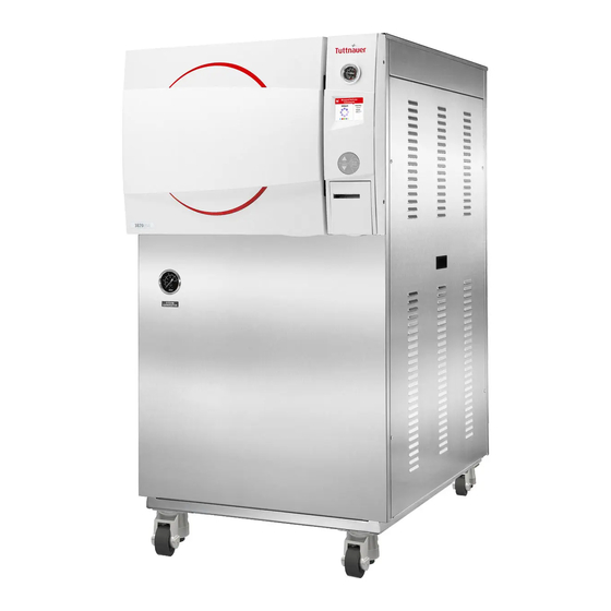
2.10 Water Quality The distilled or mineral-free water supply shall be according to the table below: Physical Characteristics and Maximum acceptable contaminants levels in water or steam, for steam generator and sterilizers (According to EN 285:2006). Contaminants in Contaminants in water supplied to condensate at steam generator... - Page 18 FRONT VIEW Description Description Chamber pressure gauge Left service door latch Control panel display USB socket Control panel keypad Printer Printer compartment door RJ45 socket Generator pressure gauge On/ Off Switch Ventilation grills Wheels Page 16 of 56 Pages...
- Page 19 REAR VIEW Description Description Wheels Circuit breaker Chamber Safety Valve Power input socket Generator Safety Valve Mineral-Free Water Overflow Chamber Strainer (WS configuration only) Manual Mineral-Free Water Inlet water fill inlet (WS configuration only) Glass tube Mechanic water level indicator water level indicator (WS configuration only) Water Generator Drain...
-
Page 20: Control Panel
CONTROL PANEL Description Display Keypad: Up Button Keypad: Start/Stop Button Keypad: Down Button Printer Page 18 of 56 Pages... -
Page 21: Description And Functions Of The Front Panel Keyboard
Description and Functions of the Front Panel Keyboard The front panel is composed of 3 sections: 1. Display screen. 2. Keypad. 3. Printer 3.1.1 Display screen The display is a LCD panel used to display the current status of the autoclave while using Operational Messages and Error Messages. - Page 22 3.1.2 Keypad The keypad consists of three keys as described below: UP key This key has the following functions: In the main screen: o This key enables the operator to browse through the cycles. In the directories available: o When the cursor is blinking on a number, the UP ▲...
-
Page 23: Displayed Error Messages / Symbols
3.1.3 Printer The printer is an optional device. It prints the detailed history of each cycle performed by the autoclave. The printing is on thermal paper with 24 characters per line and records the sterilization cycle information for subsequent consideration. Displayed Error Messages / Symbols The failures are divided into two categories. -
Page 24: Displayed Operational Messages / Symbols
Displayed operational messages / Symbols Message / Message / Symbol Symbol Required Action Description Name This symbol is displayed Close the door. when the door is open. This message is displayed Door is open when the door is opened: In Close the door to perform a (during stand standby - if START/STOP... -
Page 25: Sterilization Programs
STERILIZATION PROGRAMS The autoclave offers five sterilization programs and two test programs as follows: Sterilization Sterilization Programs Dry time Temp time (minutes) Program Description (minutes) Unwrapped 134°C instruments (273°F) Wrapped 134°C instruments (273°F) 134°C Wrapped pouches (273°F) Unwrapped delicate 121°C instruments (250°F) Wrapped delicate... -
Page 26: Program 1: Unwrapped Instruments
Program 1: Unwrapped instruments For unwrapped instruments and materials, when the manufacturer recommends autoclaving at temperatures of 134C (273F) no preset drying stage required. Nominal parameters default settings Sterilization temperature: 134C (273F) Sterilization time: 4 minutes. Drying time: 1 minute Operations Sequence ... -
Page 27: Program 2 - Wrapped Instruments
Program 2 - Wrapped instruments For wrapped instruments and materials, when the manufacturer recommends autoclaving at temperatures of 134C (273F) with a drying stage. Nominal parameters default settings Sterilization temperature: 134C (273F) Sterilization time : 4 minutes Drying time: 20 minutes (may be altered by the operator). Operations sequence: ... -
Page 28: Program 3 - Wrapped Pouches
Program 3 - Wrapped pouches For wrapped pouches and materials, when the manufacturer recommends autoclaving at temperatures of 134C (273F) with a drying stage. Nominal parameters default settings Sterilization temperature: 134C (273F) Sterilization time: 7 minutes. Drying time: 30 minutes (may be altered by the operator) Operations Sequence ... -
Page 29: Program 4 - Unwrapped Delicate Instruments
Program 4 - Unwrapped delicate instruments For unwrapped delicate instruments, when the manufacturer recommends autoclaving at temperatures of 121C (250F) with a drying stage. Nominal parameters default settings Sterilization temperature: 121C (250F) Sterilization time : 20 minutes Operations sequence: ... -
Page 30: Program 5 - Wrapped Delicate Instruments
Program 5 - Wrapped delicate instruments For wrapped delicate instruments, when the manufacturer recommends autoclaving at a temperature of 121C (250F). Nominal parameters default settings Sterilization temperature: 121C (250F). Sterilization time: 20 minutes. Drying time: 20 minutes (may be altered by the operator). Operations sequence: ... -
Page 31: Test 1 - Leak Test
TEST 1 – LEAK TEST Vacuum is produced in the chamber down to P =17 kPa. At this stage all the valves close. The autoclave remains in this stage for 5 minutes. This period enables the condition in the chamber to reach equilibrium. After the 5 minutes have elapsed the printer records the pressure that is referred to as P . - Page 32 Ambient Pressure TIME = lowest pressure level, which is equal to or lower than level set for the cycle, during the air removal and = Approx. 20 minutes = 5 minutes steam penetration stage = pressure after a period of 300 s = 10 minutes = pressure after a leakage time of 600 s Page 30 of 56 Pages...
-
Page 33: Test 2 - B&D Test
TEST 2 – B&D TEST Bowie & Dick test program, with fixed sterilization parameters 134ºC and 3.5 minutes, which cannot be modified by the operator or the technician. Nominal parameters default settings Sterilization temperature: 134ºC Sterilization time: 3.5 minutes. ... -
Page 34: Screens
SCREENS Screens following a complete successfully cycle – "Cycle Ended" 1. System Ready 2. Starting 3. Pulse L 4. Pulse H 5. Keep Heat* 6. Heat 7. Sterilization 8. Exhaust 9. Drying (option) 10. Ending 11. Cycle Ended (successfully cycle) Note: “Jacket”... -
Page 35: Screens Following Aborted Cycles After Complete Sterilization Stage
Screens following aborted cycles after complete sterilization stage The sterilization phase ended successfully – cycle ended and the reason of failure is displayed For example the next two scenarios: 5.2.1 Canceled by user after complete sterilization stage The cycle ended successfully, the reason for aborted cycle is displayed. -
Page 36: Screens Following A Fail Cycle
Screens following a fail cycle: In this case, the display becomes yellow, a warning sign and the reason of failure will be displayed. For example the next two scenarios: 7.3.1 Failure according to Pressure Time Error 7.3.2 Failure according to Cancellation by user before complete sterilization stage When "Cycle Failed"... -
Page 37: Printer
PRINTER Printer Output The printing is on thermal paper with 24 characters per line and contains the following information: Date: Time: Ser. Num: Model: Version: Cycle Num: Cycle: Dry Time: Ster Temp: ... - Page 38 PRINTER OUTPUT DESCRIPTION Operator: To be filled in manually by operator ____________ Time: 12:14:47 Time sterilization cycle ended Status: Cycle Ended 00:24:43 101.3 099.7 Cycle finished time D 00:27:40 107.0 107.4 The time, temperature and pressure during Drying Stage D 00:35:12 107.0 107.4 The time, temperature and pressure during Drying Stage...
-
Page 39: Printer Handling
Date: 9/FEB/2010 Date sterilization cycle started ----------------------- Time: 08:51:39 Time of turning on Date: 9/FEB/2010 Date of turning on POWER ON The device is turned on Time: 00:00:00 Time of turning off Date: 9/FEB/2010 Date of turning off POWER OFF The device is turned off Legend Air removal stage (Pulse L &... - Page 40 Open the printer's cover door (1) by pulling it up (see Fig. Fig. 2 Press the OPEN key to open the printer cover as shown (see Fig. 3/1). Handle the paper cutter carefully not to cut your hand. Place the paper roll making sure it unrolls in the proper direction as shown (see Fig.
-
Page 41: Treating The Thermal Papers
Treating the thermal papers: Store the papers in a dry, cool and dark place. Do not rub the papers with hard substance. Keep the papers away from organic solvent. Cautions Never disassemble the printer. Failure to follow this instruction may cause overheating or burning of the printer or the AC adapter. -
Page 42: Preparation Before Sterilization
PREPARATION BEFORE STERILIZATION The purpose of packaging and wrapping of items for sterilization is to provide an effective barrier against sources of potential contamination in order to maintain sterility and to permit aseptic removal of the contents of the pack. Packaging and wrapping materials should permit the removal of air from the pack, penetration of the sterilizing water vapor into the pack and removal of the sterilizing vapor. -
Page 43: Instruments
Instruments Place empty containers upside down to prevent accumulation of water. All instruments must be sterilized in an open position. Use single-use wraps once only and discard after use. Place a sterilization indicator strip on the tray. Place instruments with ratchets opened and unlocked or clipped on the first ratchet position. -
Page 44: Tubing
Do not place packs of hollowware and trays of instruments above textile packs or soft goods in order to avoid wetting caused by condensation from items above. Load items packed in flexible packaging materials on edge with paper to laminate, or flat with the paper surface downwards. Note: The manufacturer’s recommendations shall be observed, concerning the sterilization data for each type of material. -
Page 45: Operating Instructions
8 OPERATING INSTRUCTIONS Note: For operating the generator, refer to the operating instruction in the generator manual. Operating the autoclave Open the manual tap to the water supply network. Turning on the autoclave To start the system, turn on the main switch (1), located under the printer cover. -
Page 46: Loading
Press the Key in order to open the door The following screen will be displayed: If the door has opened successfully, the following screen will be displayed: Loading Load the autoclave properly according to instructions in sec. 9. PREPARATION BEFORE STERILIZATION. Selecting the program 1. -
Page 47: Closing The Door
Closing the door In order to close the door, follow the next steps: When the door is open, the screen below will be displayed: In order to close the door push the door to the wall of the autoclave chamber for at least 5 seconds as shown in the picture below: While closing the door the following screen will be displayed: Page 45 of 56 Pages... -
Page 48: Starting Cycle
When the door is properly closed, open door symbol is replaced by the message "System Ready" and the following screen will be displayed: Starting cycle 1. Start the cycle by pressing the START/STOP key. The autoclave starts performing sequence of operations. The actual measured values of pressure and temperature are displayed continuously and printed every minute at stage, and every 5... -
Page 49: Unloading
Unloading 1. When the cycle ended, press START/STOP key to verify the status. Message "Cycle Ended" (and the relevant failure message, if applicable) is displayed on the screen. 2. Verify that there is no pressure in the chamber, according to the reading on the display. -
Page 50: Start Cycle By Clock Mode
8.10 Start Cycle by Clock mode This mode enables the operator to define the time of the beginning of the cycle. The maximum possible delay is 24 hours. For further information see sec. 6.8.1. “Start Cycle by Clock”. 9 SERVICE AND MAINTENANCE Preventive and Scheduled Maintenance The maintenance operations described in this chapter have to be fulfilled periodically to keep the device in good condition and to reduce the... -
Page 51: Cleaning Water Strainer
2. Check the door gasket every 12 months and replace it if required (see para. 9.5). Replacing the gasket shall be done by a technician. 3. Once a year check and tighten the piping joints to avoid leakage. 4. Once a year check and tighten all screw connections in the control box, heaters and valves and instrumentation. -
Page 52: Checking The Safety Valve
Do not touch the strainer’s cover, mounted on the exhaust line, during and short after operation. Touching the hot strainer’s cover may cause severe injuries. Checking the Safety Valve Both safety valves, the chamber safety valve (2) and the generator safety valve (3), are located on the top rear of the autoclave (see Rear View, 14 and 15). - Page 53 9.3.2 ASME-approved type safety valve For the autoclave safety valve, operate the sterilization cycle; for the generator safety valve, operate the generator. Allow a pressure of approximately 200 kPa (29-psi) to build up in the chamber. Operate the safety valve by pulling the ring of the safety valve using a tool, i.e.
- Page 54 9.3.3 Replacing the Air Filter In order to “break” the vacuum, at the end of the dry phase, filtered atmospheric air enters the chamber via a solenoid valve. The filtration of the air is performed by the bacteriological filter that is placed at the inlet of the chamber, through a solenoid valve.
-
Page 55: 10 Troubleshooting
10 TROUBLESHOOTING This troubleshooting chart enables the user to solve minor malfunctions, prior to contacting our service department. Only technical personnel having proper qualifications and holding technical documentation (including a technician manual) and adequate information are authorized to service the apparatus. Problem / Failure Message / Symbol Description... - Page 56 "Heat Time The system cannot reach the required Check that the autoclave is not Error" is temperature, in the chamber, within the overloaded. displayed. preset time. Pressure drops below the sterilization "Low pressure (134°C = 304 kPa, 121°C = 205 Pressure"...
- Page 57 POUCH RACK TRH387-0006 TRAY TRAY CAT. NO. TRY387-0001 Small TRY387-0003 TRAY HOLDER TRH387-0001 Page 55 of 56 Pages...
-
Page 58: 11 Spare Parts List
11 SPARE PARTS LIST PART NUMBER DESCRIPTION FIL175-0046 Strainer element, 400µ FIL175-0027 Cap for¼” strainer GAS082-0008 Teflon gasket 4mm 12 ACSSESORIES LIST PART NUMBER Description ACS215-0008 Pouch rack (available upon request) THE002-0052 Printer paper TRY387-0005 Tray BSK387-0006 Basket BSK387-0004 Container (available upon request) Page 56 of 56 Pages...
Need help?
Do you have a question about the 3870 HSG-D and is the answer not in the manual?
Questions and answers
the door is not opening