
Related Manuals for NetterVibration PKL Series


Summary of Contents for NetterVibration PKL Series
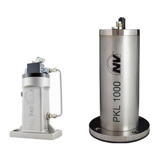
- Page 1 Operating instructions for June 2020 No. 1468E Netter pneumatic impactors Page 1/26 of the series PKL These operating instructions apply to: PKL 190 PKL 1000 PKL 450 PKL 2100 PKL 740 PKL 5000 PKL 10000...
-
Page 2: Table Of Contents
Contents General information Safety Technical data Design and function Transport and storage Installation Start-up and operation Maintenance and servicing Troubleshooting Spare parts and accessories Disposal Annex Please refer to the delivery note for the scope of delivery. Scope of delivery Check the packaging for possible transport damage. -
Page 3: General Information
General information General information Before installing the PKL read these instructions carefully. It is the basis Use and for any action when dealing with the PKL, and may be used for training storage purposes. The instructions should be subsequently stored at the operation site. - Page 4 General information Instruction The following instruction and warning symbols are used in these instruc- and warning tions: symbols Personal DANGER injuries signifies an immediate danger. Disregard of this notice will result in death or severe bodily injuries. WARNING signifies a potential danger. Disregard of this notice can result in death or severe bodily injuries.
-
Page 5: Safety
Safety Safety General areas of application of the PKL are for knocking off adhesive bulk Intended use materials from container walls (e.g. silos, hoppers, filter outlets, pipelines and reactors) and for emptying residues from weighing containers. The PKL also prevent bridging and rat-holing, so that the material can continu- ously flow. - Page 6 Safety Compressed WARNING Compressed air A loosened hose which is under pressure can lead to personal injuries. ➢ Screw the hose lines on carefully. ➢ Check the hose lines and connections after one hour of operation and thereafter regularly (generally monthly). ➢...
-
Page 7: Technical Data
15 strokes/min and 180 strokes/h. * Higher operating pressures and temperatures are permitted only after consultation with and written consent by the application technicians of NetterVibration. The type designations of the PKL have the suffix /3, /4, /5 or /6. The suffix Type is derived from the optimum operating pressure, i.e. - Page 8 Technical data Parameters Type: Weight Force of Optimum Air consump- Overall Suitable PKL ... of piston impact * operating tion/impact at opti- weight for wall pressure mum pressure thickness of... [bar] [Nl] [kg] [kg] [kg] [mm] 190/4 0.19 0.43 0.20 1 - 2 190/6 0.19...
- Page 9 Technical data PKL 1000 PKL 10000 Dimensions PKL 2100 PKL 5000 1000 / 2100 / 5000 / 10000 Type: Ø A Ø B Ø D Ø G PKL ... [mm] [mm] [mm] [mm] [mm] [mm] [mm] 1000 88.9 G 1/8, DN 6 ×...
-
Page 10: Design And Function
Design and function Design and function Design Quick air-exhaust valve Silencer Springs Piston Flange Impact plate Pressure Impact force The PKL is a pneumatic "hammer". Compressed air goes under the pis- Function ton (4) and presses it against one or two springs (3). When exhausting, the air chamber beneath the piston empties abruptly via the quick air-exhaust valve (1). -
Page 11: Transport And Storage
Transport and storage Transport and storage Observe the safety instructions in Ch. Safety, from page 5 on. Special transport conditions are not required. Transport conditions When moving the PKL 10000, use the mounted transport lugs at the top of the housing. Packaging The PKL are packed and ready for assembly. -
Page 12: Installation
Installation Installation Observe the safety instructions in Ch. Safety, from page 5 on. When installing the PKL carry out the following steps in succession: Procedure Instructions Install the EE kit on the PKL 190 / 450 / 740 between the flange of the PKL for EE kit and the mounting surface so that •... - Page 13 Installation Instructions Install the EE kit on the PKL 1000 / 2100 / 5000 / 10000 as follows: for EE kit Remove the steel impact plate with the O-ring (2) and the damper ring (impact plate) (1). 1000 / Insert the EE impact plate with the O-ring (3) in such a way that the 2100 / piston of the PKL strikes against the EE impact plate (3).
- Page 14 Installation Fixing Appropriate fixing devices (±0.1 mm flatness): devices weld-on consoles, weld-on plates, glueing consoles • Weld the weld-on consoles directly onto the container walls. • Weld the plates onto previously mounted saddle plates (1.5 times the sheet thickness of the container). •...
- Page 15 Installation Instructions Components of the fastening kit using the fastening kit example NBS D: Hexagon bolt NBS lock plate Washer Damper spring Washer (only for NBS D) Tab washer with long tap (here only for NBS D) Nut (only for NBS D) The damping springs must be mounted on the flange of the PKL.
- Page 16 Installation Instructions The ST kit connects the control port to the piston chamber. The PKL for ST kit equipped with the ST kit strikes as long as there is compressed air. • For PKL 190 / 450 proceed as follows: - Mount the ST screw fitting (after the NBS).
- Page 17 Installation Standard Example: PKL 450 Use a 3/2-way valve (4) for ac- installation tuation. all types of By switching the valve, the pis- PKL except ton chamber is vented and ex- hausted and the PKL therefore strikes. Mount the 3/2-way valve (4) at a distance of max.
- Page 18 Installation Installation Example: PKL 450 The main air is always at the with long 3/2-way valve (5) max. 1 m supply line away from the PKL. The control all types of line from the actuating valve (4) PKL except on the customer's site to the PKL may be longer (e.g.
- Page 19 Installation Installation Example: PKL 2100 The PKL, equipped with an ST with ST kit kit (1), strikes as long as pressure is applied. The PKL thereby 190 / achieves a maximum impact fre- 450 / quency of up to one strike per 2100 / second, which must be reduced 5000...
- Page 20 Installation Installation Example: PKL 2100 If the PKL is equipped with an with coupling ST kit, then it can be coupled to other with another function without a functions control or a pulse generator. The adjacent illustration shows the coupling with an opening cylinder (3) of a weighing con- tainer.
-
Page 21: Start-Up And Operation
Start-up and operation Start-up and operation Observe the safety instructions in Ch. Safety, from page 5 on. Please refer to Ch. Technical data, page 7 for permissible operating condi- Permissible tions. operating conditions Design of For installation with mist lubricator: mist lubricator When selecting the mist lubricator, take into consideration that the air con- sumption of the PKL is very low. -
Page 22: Maintenance And Servicing
Maintenance and servicing Maintenance and servicing Observe the safety instructions in Ch. Safety, from page 5 on. Maintenance of the PKL must be carried out as follows: Maintenance plan Interval Action After one hour of opera- Check fastening screws. tion after initial commis- Check hose screw connections and hose connections and sioning retighten, if necessary. -
Page 23: Troubleshooting
Troubleshooting Troubleshooting In the case of malfunctions of the PKL proceed as follows: Malfunctions and causes Malfunction Possible causes Corrective actions Does not function Mounting surface not flat, loss Establish ±0.1 mm flatness on of pressure via O-ring mounting surface. Malfunction of valve and con- Check PKL without valve and trol... -
Page 24: Spare Parts And Accessories
Spare parts and accessories 10 Spare parts and accessories Please provide the following details when ordering spare parts: Ordering of spare parts • required amount • description and position of spare part • type of PKL Possible Following accessories for the PKL are available: accessories Accessory Description... -
Page 25: Disposal
Disposal 11 Disposal Prices All parts of the PKL must be properly disposed of according to the material specifications. The valid disposal prices of the PKL are available on request. Material Type Steel or stainless Aluminium Plastics steel specifications PKL 190 Impact piston, com- Housing, EE spacer Seals, membrane,... -
Page 26: Annex
Annex 12 Annex Declaration of Incorporation...
Need help?
Do you have a question about the PKL Series and is the answer not in the manual?
Questions and answers