
Related Manuals for HBK RTN/M2


Summary of Contents for HBK RTN/M2
- Page 1 ENGLISH DEUTSCH FRANÇAIS ESPAÑOL Mounting Instructions Montageanleitung Notice de montage Instrucciones de montaje RTN/M2 RTN/M2LAR, RTN/M2LA, RTN/M2LBR, RTN/M2LB...
- Page 2 Hottinger Brüel & Kjaer GmbH Im Tiefen See 45 D-64293 Darmstadt Tel. +49 6151 803-0 Fax +49 6151 803-9100 info@hbkworld.com www.hbkworld.com Mat.: 7-2001.1088 DVS: A01867 02 YS0 03 05.2022 E Hottinger Brüel & Kjaer GmbH Subject to modifications. All product descriptions are for general information only.
- Page 3 ENGLISH DEUTSCH FRANÇAIS ESPAÑOL Mounting Instructions RTN/M2 RTN/M2LAR, RTN/M2LA, RTN/M2LBR, RTN/M2LB...
-
Page 4: Table Of Contents
............Specifications RTN/M2L... weighing modules ......RTN/M2 TABLE OF CONTENTS... -
Page 5: Safety Instructions
Environmental conditions In the context of your application, please note that all materials which release chlorine ions will attack all grades of stainless steel and their welding seams. In such cases the operator must take appropriate safety measures. RTN/M2 SAFETY INSTRUCTIONS... - Page 6 With environmental conditions that cannot be clearly defined, HBK recommends to provide the load cells and weighing modules with a protective coating which matches these conditions (after mounting) in order to prevent the influence of aggressive media. Please take into account the resistance of the cable material and the mounting parts.
-
Page 7: Markings Used
This marking draws your attention to information Information about the product or about handling the product. Emphasis Italics are used to emphasize and highlight text and See … identify references to sections, diagrams, or external documents and files. RTN/M2 MARKINGS USED... -
Page 8: General
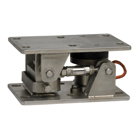
GENERAL HBK offers the RTN/M2(L)... weighing module for RTN load cells with max. capacities of 1 t ... 33 t. The ”L” in the type designation signifies that the module has been fitted with a stay rod. “A” signifies rubber‐metal bearing, “B” stands for pendulum bearing. - Page 9 (with RTN/M2LA) or a pendulum bearing (with RTN/M2LB) is used which allows for horizontal shifting of the load applied. The weighing modules are completely fitted with a load cell dummy that can be loaded, with a ground cable, and a securing device for transport. RTN/M2 GENERAL...
-
Page 10: Mounting Preparation
(provide spacer plates, 5 x 1 mm included in scope of delivery). Undo transport protection device and stops, fit height adjustment plates (dependent on maximum capacity, see Dimensions). RTN/M2 MOUNTING PREPARATION... - Page 11 Five plates max. are to be fitted underneath the upper module plate, and five plates max. between the base and the cross bracket of the anti‐liftoff device Important Ensure that all screws are fitted with U‐washers. RTN/M2 MOUNTING PREPARATION...
- Page 12 (only up to 4.7 t 5 plates max. for height adjustment Centering disc max. capacity) (only up to 4.7 t max. capacity) Cross‐bracket (Anti‐liftoff device) Lateral stops Fig. 4.1 Fitting of the spacer plates with 4.7 t version RTN/M2 MOUNTING PREPARATION...
- Page 13 5 plates max. for height adjustment Air gap: 1 mm Dummy Bearing 5 plates max. for height adjustment Cross‐bracket (Anti‐liftoff device) Lateral stops Fig. 4.2 Fitting of the spacer plates with 10 t ... 33 t version RTN/M2 MOUNTING PREPARATION...
-
Page 14: Mounting
Remove mounting from dummy and fit to load cell; tightening torque of the 4 screws: 4 N⋅m Secure and position load cell with mounting base by means of centering discs on the lower module plate. Apply the enclosed grease to the load introduction parts of the load cell. RTN/M2 MOUNTING... - Page 15 The stay rods already have been adjusted at the factory to ensure that the load introduction parts are aligned with the load cell in the rod direction. Should a readjustment prove necessary, the rod end bearings subsequently have to be carefully locked. RTN/M2 MOUNTING...
- Page 16 The movement tolerance of the stay rod should be checked regularly and readjusted, if necessary. RTN/M2 MOUNTING...
-
Page 17: Dimensions
DIMENSIONS RTN/M2LA - Version with rubber‐metal bearing Max. capacity 1 t ... 4,7 t max. 5 spacer plates only version with stay rod View from above Perspective view View from below Dimensions in mm (1mm = 0.03937 inches) RTN/M2 DIMENSIONS... - Page 18 RTN/M2LA - Version with rubber‐metal bearing Max. capacity 10 t ... 22 t max. 5 spacer plates only version with stay rod View from above Perspective view View from below Dimensions in mm (1mm = 0.03937 inches) RTN/M2 DIMENSIONS...
- Page 19 RTN/M2LA - Version with rubber‐metal bearing Max. capacity 33 t max. 5 spacer plates only version with stay rod View from above Perspective view View from below Dimensions in mm (1mm = 0.03937 inches) RTN/M2 DIMENSIONS...
- Page 20 RTN/M2LB - Version with pendulum bearing Max. capacity 1 t ... 4.7 t max. 5 spacer plates only version with stay rod View from above Perspective view View from below Dimensions in mm (1mm = 0.03937 inches) RTN/M2 DIMENSIONS...
- Page 21 RTN/M2LB - Version with pendulum bearing Max. capacity 10 t ... 22 t max. 5 spacer plates only version with stay rod View from above Perspective view View from below Dimensions in mm (1mm = 0.03937 inches) RTN/M2 DIMENSIONS...
- Page 22 RTN/M2LB - Version with pendulum bearing Max. capacity 33 t max. 5 spacer plates only version with stay rod View from above Perspective view View from below Dimensions in mm (1mm = 0.03937 inches) RTN/M2 DIMENSIONS...
-
Page 23: Specifications Rtn/M2L
Rubber‐metal bearing Neoprene (Chlorbutadien caoutchouc) Weight (with dummy), 10.5 21.5 44.5 approx. Min. lifting height for installing the load cell Height adjustment (spacer plates in scope of delivery) These specifications are based on DIN 18800 According to EN 10088-1 RTN/M2 SPECIFICATIONS... - Page 24 1-RTN/M2LAR4.7T WITH stay rod 4.7 t stainless steel 1-RTN/M2AR4.7T WITHOUT stay rod 1-RTN/M2LAR22T WITH stay rod 10 t ... 22 t stainless steel 1-RTN/M2AR22T WITHOUT stay rod 1-RTN/M2LA33T WITH stay rod 33 t galvanized 1-RTN/M2A33T WITHOUT stay rod RTN/M2 SPECIFICATIONS...
- Page 25 Order number Max. capacity Material Version for load cell 1-RTN/M2LBR4.7T/2 WITH stay rod 1 t ... 4.7 t stainless steel 1-RTN/M2BR4.7T/2 WITHOUT stay rod 1-RTN/M2LBR22T WITH stay rod 10 t ... 22 t stainless steel 1-RTN/M2BR22T WITHOUT stay rod RTN/M2 SPECIFICATIONS...
- Page 26 120° Stay rod Load introduction 90° 90° Degree of freedom Attention: The represented bearing arrangements con sider only weighing‐techni cal criteria. The carrying and stability 90° 90° must be examined and guaranteed in each case by the operator. RTN/M2 SPECIFICATIONS...
- Page 27 ENGLISH DEUTSCH FRANÇAIS ESPAÑOL Montageanleitung RTN/M2 RTN/M2LAR, RTN/M2LA, RTN/M2LBR, RTN/M2LB...
- Page 28 ........... . Technische Daten der Wägemodule RTN/M2L......RTN/M2 INHALTSVERZEICHNIS...
-
Page 29: Sicherheitshinweise
Jeweils existierende Vorschriften sind zu beachten. Auf Restgefahren im Zusammenhang mit der Wägetechnik ist hinzuweisen. Umgebungsbedingungen Beachten Sie in Ihrem Anwendungsfeld, dass alle Stoffe die (Chlor‐)Ionen freisetzen, auch nichtrostende Stähle und deren Schweißnähte angreifen. In diesem Fall sind von der Betreiberseite entsprechende Schutzmaßnahmen vorzusehen. RTN/M2 SICHERHEITSHINWEISE... - Page 30 HBK empfiehlt bei nicht eindeutig geklärten Umweltbedingungen, die Wägezellen und Wägemodule mit einem, auf die Bedingungen abgestimmten Schutzanstrich (im mon tierten Zustand), zu versehen, um den Einfluss von aggressiven Medien fernzuhalten. Beachten Sie die Beständigkeit des Kabelmaterials und der Einbauelemente.
-
Page 31: Verwendete Kennzeichnungen
Sie nützliche Informationen hin. Diese Kennzeichnung weist auf Informationen zum Information Produkt oder zur Handhabung des Produktes hin. Hervorhebung Kursive Schrift kennzeichnet Hervorhebungen im Text Siehe … und kennzeichnet Verweise auf Kapitel, Bilder oder externe Dokumente und Dateien. RTN/M2 VERWENDETE KENNZEICHNUNGEN... -
Page 32: Allgemeines
ALLGEMEINES HBK bietet das Wägemodul RTN/M2(L)AR..., RTN/M2(L)BR... für RTN‐Wägezellen in den Nennlastbereichen 1 t...33 t an. Das “L” in der Typenbezeichnung bedeutet, das Wäge modul ist mit einem Lenker ausgerüstet. “A” bedeutet mit Gummi‐Metall‐Lager, “B” steht für Pendellager. Produktvarianten RTN/M2LA... - Page 33 Modulplatte zur Behältermontage. Als Lasteinleitungselement in die Wägezelle dient ein Gummi‐Metall‐Lager (bei RTN/M2LA), bzw. ein Pendellager (bei RTN/M2LB), welches horizontale Verschiebungen der aufgebrachten Last ermöglicht. Die Wägemodule sind komplett mit einem belastbaren Wägezellen‐Dummy, Erdungskabel und Transportsicherung montiert. RTN/M2 ALLGEMEINES...
-
Page 34: Montagevorbereitung
Lagerung für eine korrekte Einstellung des Höhenniveaus an den Lagerpunkten Sorge getragen werden (Ausgleichsbleche bereit halten, 5 x 1 mm, im Lieferumfang enthalten). Transportsicherung und Anschläge lösen. Bleche für Höhenausgleich einbauen. (Nennlastabhängig, siehe Abmessungen) RTN/M2 MONTAGEVORBEREITUNG... - Page 35 Im Lieferumfang des Moduls sind 2 x 5 Ausgleichsbleche enthalten. Sie dienen zum Aus richten des Moduls. Maximal fünf Bleche sind unter der oberen Modulplatte und maximal fünf Bleche zwischen dem Sockel und Riegel der Abhebesicherung unterzulegen. Wichtig Achten Sie darauf, dass alle Schrauben mit U‐Scheiben montiert sind. RTN/M2 MONTAGEVORBEREITUNG...
- Page 36 Obere Modulplatte Höhenausgleich Luftspalt 1 mm Lager Dummy Grundplatte (nur bis Nennlast 4,7 t) Zentrierscheibe (nur max. 5 Bleche für Höhenausgleich bis Nennlast 4,7 t) Querriegel (Abhebesicherung) seitliche Anschläge Abb. 4.1 Montage der Ausgleichsbleche bei Ausführung 4,7 t RTN/M2 MONTAGEVORBEREITUNG...
- Page 37 5 Bleche für Obere Modulplatte Höhenausgleich Luftspalt 1 mm Dummy Lager max. 5 Bleche für Höhenausgleich seitliche Anschläge Querriegel (Abhebesicherung) Abb. 4.2 Montage der Ausgleichsbleche bei Ausführung 10 t .. 33 t RTN/M2 MONTAGEVORBEREITUNG...
-
Page 38: Montage
Lösen der Zentrierscheiben Entfernen des Dummys mit der Grundplatte der RTN durch leichtes Anheben und seit liche Entnahme (bei Pendellagerausführung mit Pendellager) Demontieren der Grundplatte vom Dummy und Montage an die Wägezelle, Anzugs moment der 4 Schrauben: 4 N⋅m RTN/M2 MONTAGE... - Page 39 Daten Kapitel 7 zu entnehmen. Die Lenker sind ab Werk bereits voreinge stellt, so dass in Lenkerrichtung die Lasteinleitungsteile mit der Wägezelle fluchten. Falls doch eine Nachstellung erforderlich werden sollte, sind die Gelenkköpfe anschließend sorgfältig zu kontern. RTN/M2 MONTAGE...
- Page 40 Horizontale Verschiebungen, die über den maximal zulässigen Wert hinausgehen und nicht in Lenkerrichtung wirken, sind durch entsprechende Ausrichtung der anderen Module zu vermeiden oder durch anderweitige Anschläge bzw. Vorrichtungen auf zunehmen. Das Bewegungsspiel des Lenkers sollte regelmäßig kontrolliert und gegebenenfalls nachjustiert werden. RTN/M2 MONTAGE...
-
Page 41: Abmessungen
ABMESSUNGEN RTN/M2LA - Ausführung mit Gummi‐Metall‐Lager Nennlast 1 t ... 4,7 t max. 5 Ausgleichsbleche nur bei Ausführung mit Lenker Ansicht von oben Perspektivische Ansicht Ansicht von unten Abmessungen in mm RTN/M2 ABMESSUNGEN... - Page 42 RTN/M2LA - Ausführung mit Gummi‐Metall‐Lager Nennlast 10 t ... 22 t max. 5 Ausgleichsbleche nur bei Ausführung mit Lenker Ansicht von oben Perspektivische Ansicht Ansicht von unten Abmessungen in mm RTN/M2 ABMESSUNGEN...
- Page 43 RTN/M2LA - Ausführung mit Gummi‐Metall‐Lager Nennlast 33 t max. 5 Ausgleichsbleche nur bei Ausführung mit Lenker Ansicht von oben Perspektivische Ansicht Ansicht von unten Abmessungen in mm RTN/M2 ABMESSUNGEN...
- Page 44 RTN/M2LB - Ausführung mit Pendellager Nennlast 1 t ... 4,7 t max. 5 Ausgleichsbleche nur bei Ausführung mit Lenker Ansicht von oben Perspektivische Ansicht Ansicht von unten Abmessungen in mm RTN/M2 ABMESSUNGEN...
- Page 45 RTN/M2LB - Ausführung mit Pendellager Nennlast 10 t ... 22 t max. 5 Ausgleichsbleche nur bei Ausführung mit Lenker Ansicht von oben Perspektivische Ansicht Ansicht von unten Abmessungen in mm RTN/M2 ABMESSUNGEN...
- Page 46 RTN/M2LB - Ausführung mit Pendellager Nennlast 33 t max. 5 Ausgleichsbleche nur bei Ausführung mit Lenker Ansicht von oben Perspektivische Ansicht Ansicht von unten Abmessungen in mm RTN/M2 ABMESSUNGEN...
-
Page 47: Technische Daten Der Wägemodule Rtn/M2L
Stahl Metallteile Gummi‐Metall‐Lager Neopren (Chlorbutadien‐Kautschuk) Gewicht (mit Dummy), 10,5 21,5 44,5 Minimale Hubhöhe zum Einbau der WZ Höhenausgleich durch mitgelieferte Beilege bleche Die Angaben erfolgen auf Basis der DIN 18800 Nach EN 10088‐1 RTN/M2 TECHNISCHE DATEN... - Page 48 Nichtrostender Stahl 1-RTN/M2AR2.2T OHNE Lenker 1-RTN/M2LAR4.7T MIT Lenker 4,7 t Nichtrostender Stahl 1-RTN/M2AR4.7T OHNE Lenker 1-RTN/M2LAR22T MIT Lenker 10 t ... 22 t Nichtrostender Stahl 1-RTN/M2AR22T OHNE Lenker 1-RTN/M2LA33T MIT Lenker 33 t Galvanisch verzinkt 1-RTN/M2A33T OHNE Lenker RTN/M2 TECHNISCHE DATEN...
- Page 49 Ausführung 1-RTN/M2LBR4.7T/2 MIT Lenker 1 t ... 4,7 t Nichtrostender Stahl 1-RTN/M2BR4.7T/2 OHNE Lenker 1-RTN/M2LBR22T MIT Lenker 10 t ... 22 t Nichtrostender Stahl 1-RTN/M2BR22T OHNE Lenker 1-RTN/M2LB33T MIT Lenker 33 t Galvanisch verzinkt 1-RTN/M2B33T OHNE Lenker RTN/M2 TECHNISCHE DATEN...
- Page 50 Montagebeispiele für Wägemodule mit Lenker 120° 120° 120° Lenker Lasteinleitung Freiheitsgrad 90° 90° Achtung: Die dargestellten Lager ordnungen berücksichtigen nur wägetechnische Gesichtspunkte. 90° 90° Die Trag‐ und Stand sicherheit muss in jedem Fall vom Betreiber geprüft und sichergestellt werden. RTN/M2 TECHNISCHE DATEN...
- Page 51 ENGLISH DEUTSCH FRANÇAIS ESPAÑOL Notice de montage RTN/M2 RTN/M2LAR, RTN/M2LA, RTN/M2LBR, RTN/M2LB...
- Page 52 ............Caractéristiques techniques RTN/M2...
-
Page 53: Consignes De Sécurité
à minimiser les dangers résiduels. Les dispositions en vigueur doivent être res pectées. Il convient de souligner les dangers résiduels liés aux techniques de pesage. RTN/M2 CONSIGNES DE SÉCURITÉ... - Page 54 L'exploitant doit donc prévoir des mesures de protection correspondantes. Lorsque les conditions environnantes n'ont pas été rendues claires et distinctes, HBK recommande d'appliquer un enduit de protection sur les pesons et les modules de pesages qui convient à...
-
Page 55: Marquages Utitlsés
Ce marquage signale que des informations Information concernant le produit ou sa manipulation sont fournies. Mise en valeur Pour mettre en valeur certains mots du texte, Voir … ces derniers sont écrits en italique. RTN/M2 MARQUAGES UTITLSÉS... -
Page 56: Généralités
Pour la famille de pesons RTN, HBK propose maintenant un module à intégrer baptisé RTN/M2(L)..., pour des capacités maxi de 1 à 33 tonnes. Le “L” dans la désignation sig nifie qu'il s'agit d'un module avec tirant transversal. Le “A” signifie palier élastomère, le “B”... - Page 57 Les modules de pesage sont livrés entièrement montés avec un faux peson qui peut être chargé, un câble de mise à la terre et une sécurité de transport. RTN/M2 GÉNÉRALITÉS...
-
Page 58: Préparatifs Au Montage
5 x 1 mm, inclues dans l'étendue de livraison). Enlever la sécurité de transport ainsi que les butées, mettre en place les tôles de com pensation en hauteur (dépendant de la capacité maxi, voir Dimensions). RTN/M2 PRÉPARATIFS AU MONTAGE... - Page 59 On ne pourra mettre en place respectivement que cinq tôles sous la plaque module supérieure et autant entre le socle et le verrou de la sécurité anti‐soulèvement. Information Veiller à ce que toutes les vis soient montées avec des rondelles en U. RTN/M2 PRÉPARATIFS AU MONTAGE...
- Page 60 Rondelle de centrage (sur 5 tôles, maxi, pour la com modules à capacité maxi 4,7t) pensation en hauteur Verrou transversal (Sécurité anti‐soulèvement) Butées latérales Fig. 4.1 Montage des tôles de compensation avec la version 4,7 t RTN/M2 PRÉPARATIFS AU MONTAGE...
- Page 61 Inter stice: 1 Mannequin Palier 5 tôles, maxi, pour la compensation en hauteur Butées latérales Verrou transversal (Sécurité anti‐soulèvement) Fig. 4.2 Montage des tôles de compensation avec la version 10 t ... 33 t RTN/M2 PRÉPARATIFS AU MONTAGE...
-
Page 62: Montage
Soulever d'environ 10 mm chacun des pieds du réservoir, à l'aide d'un dispositif de levage approprié. Enlever les rondelles de centrage. Retirer le faux peson avec la plaque de fondation par le côté, après l'avoir légèrement soulevé (avec la version à palier oscillant : avec le palier oscillant). RTN/M2 MONTAGE... - Page 63 Les tirants ont été ajusté à l'usine afin que les éléments d'indtroduction des charges s'alignent au peson. Si un rajustement s'avère nécessaire, les rotules doivent ensuite être bloquées soigneuse ment. RTN/M2 MONTAGE...
- Page 64 être évités par l'alignement adéquat des autres modules, ou par la mise en place d'autres butées ou dispositifs analogues Vérifier périodiquement le jeu du tirant et, le cas échéant, rajuster celui‐ci. RTN/M2 MONTAGE...
-
Page 65: Dimensions
DIMENSIONS RTN/M2LA - version avec palier élastomère Capacité maxi 1 t ... 4,7 t 5 tôles de compensation, max. seulement version avec contrefléau Vue de dessus Vue perspective Vue de dessous Dimensions en mm RTN/M2 DIMENSIONS... - Page 66 RTN/M2LA - version avec palier élastomère Capacité maxi 10 t ... 22 t 5 tôles de compensation, max. seulement version avec contrefléau Vue de dessus Vue perspective Vue de dessous Dimensions en mm RTN/M2 DIMENSIONS...
- Page 67 RTN/M2LA - version avec palier élastomère Capacité maxi 33 t 5 tôles de compensation, max. seulement version avec contrefléau Vue de dessus Vue perspective Vue de dessous Dimensions en mm RTN/M2 DIMENSIONS...
- Page 68 RTN/M2LA - version avec palier oscillant 5 tôles de compensation, max. Capacité maxi 1 t ... 4,7 t seulement version avec contrefléau Vue de dessus Vue perspective Vue de dessous Dimensions en mm RTN/M2 DIMENSIONS...
- Page 69 RTN/M2LA - version avec palier oscillant Capacité maxi 10 t ... 22 t 5 tôles de compensation, max. seulement version avec contrefléau Vue de dessus Vue perspective Vue de dessous Dimensions en mm RTN/M2 DIMENSIONS...
- Page 70 RTN/M2LA - version avec palier oscillant Capacité maxi 33 t 5 tôles de compensation, max. seulement version avec contrefléau Vue de dessus Vue perspective Vue de dessous Dimensions en mm RTN/M2 DIMENSIONS...
-
Page 71: Caractéristiques Techniques Rtn/M2
CARACTÉRISTIQUES TECHNIQUES RTN/M2... RTN/M2LA... (version avec palier élastomère) RTN/ RTN/ RTN/ RTN/ Type M2LAR2.2T M2LAR4.7T M2LAR22T M2LA33T Capacité maxi (E ) du 10 15 capteur de pesage Charge limite Charge maxi admis des % de butées latérales transverse à la direc... - Page 72 1-RTN/M2AR2.2T SANS tirant 1-RTN/M2LAR4.7T AVEC tirant 4,7 t acier inoxydable 1-RTN/M2AR4.7T SANS tirant 1-RTN/M2LAR22T AVEC tirant 10 t ... 22 t acier inoxydable 1-RTN/M2AR22T SANS tirant 1-RTN/M2LA33T AVEC tirant 33 t acier étamé 1-RTN/M2A33T SANS tirant RTN/M2 CARACTÉRISTIQUES TECHNIQUES...
- Page 73 Selon EN 10088‐1 Versions disponibles RTN/M2LB... de commande Capacité maxi Matériau Version 1-RTN/M2LBR4.7T/2 AVEC tirant 1 t ... 4,7 t acier inoxydable 1-RTN/M2BR4.7T/2 SANS tirant 1-RTN/M2LBR22T AVEC tirant 10 t ... 22 t acier inoxydable 1-RTN/M2BR22T SANS tirant RTN/M2 CARACTÉRISTIQUES TECHNIQUES...
- Page 74 90° Attention: Les dispositions des pali ers représentées ne con sidèrent que les aspects de pesage. La sécurité de support et la stabilité stati 90° 90° que doivent en tout cas être vérifiées et assurées par l'opérateur. RTN/M2 CARACTÉRISTIQUES TECHNIQUES...
- Page 75 ENGLISH DEUTSCH FRANÇAIS ESPAÑOL Instrucciones de montaje RTN/M2 RTN/M2LAR, RTN/M2LA, RTN/M2LBR, RTN/M2LB...
- Page 76 ........... . . Características técnicas RTN/M2L........RTN/M2 ÍNDICE...
-
Page 77: Instrucciones De Seguridad
Deben cumplirse todas las normas respectivas existentes. Se debe informar sobre los posibles peligros relacionados con la técnica de pesaje. RTN/M2 INSTRUCCIONES DE SEGURIDAD... - Page 78 Si esto fuera inevitable, el explotador deberá tomar las medidas de protección pertinentes. HBK recomienda en condiciones ambientales no especificadas aplicar una capa de pin tura protectora determinada según las condiciones sobre las células de carga y módulos de pesaje una vez montados a fin de evitar la influencia de medios agresivos.
-
Page 79: Marcados Utilizados
útiles para el usuario. Esta señalización introduce información sobre el Información producto o su utilización. Cursiva La letra en cursiva indica el énfasis en el texto y Véase… señala referencias a los capítulos, imágenes o do cumentos y archivos externos. RTN/M2 MARCADOS UTILIZADOS... -
Page 80: Generalidades
GENERALIDADES HBK ofrece el módulo de pesaje RTN/M2(L)AR.., RTN/M2(L)BR... para la célula de carga RTN en los márgenes de carga nominal de 1 t hasta 33 t. Una “L” en la denominación del tipo significa que el módulo de pesaje está equipado con una biela. Asimismo, una “A”... - Page 81 M2LA) y un cojinete de péndulo (en los RTN/M2LB), los cuales permiten los desplazam ientos horizontales de la carga aplicada. Los módulos de pesaje se suministran com pletamente montados, con una resistente célula de carga postiza, cable de puesta a tierra y protección para el transporte. RTN/M2 GENERALIDADES...
-
Page 82: Preparación Del Montaje
(disponer las placas nivela doras, 5 x 1 mm, contenidas en el suministro). Soltar el seguro para transporte y los topes. Montar las placas para la nivelación de alturas en función de la carga nominal; consultar las dimensiones. RTN/M2 PREPARACIÓN DEL MONTAJE... - Page 83 Se pueden colocar un máximo de 5 placas debajo de la placa módulo superior y un máximo de 5 placas entre el zócalo y travesaño de la seguridad de levanta miento. Importante Verificar que todos los tornillos cuenten con arandelas. RTN/M2 PREPARACIÓN DEL MONTAJE...
- Page 84 5 placas para nivelar alturas Arandela de centrado nominal 4,7 t) (solo hasta carga nominal 4,7 t) Travesaño (seguridad de levantamiento) Topes laterales Fig. 4.1 Montaje de las placas niveladoras en la versión de 4,7 t RTN/M2 PREPARACIÓN DEL MONTAJE...
- Page 85 5 placas para nivelar alturas Separación: 1 mm Postiza Cojinete máx. 5 placas para nivelar alturas Topes laterales Travesaño (seguridad de levantamiento) Fig. 4.2 Montaje de las placas niveladoras en la versión de 10 t a 33 t RTN/M2 PREPARACIÓN DEL MONTAJE...
-
Page 86: Montaje
(en caso de la versión con cojinete de péndulo, retirar tam bién dicho cojinete). Desmontar la placa base montada a la célula de carga postiza y montarla a la célula de carga verdadera con un par de apriete de los cuatro tornillos de 4 N⋅m. RTN/M2 MONTAJE... - Page 87 (columna de los topes) se pueden consultar en las características técnicas del capítulo 7. Las bielas vienen ajustadas de fábrica de modo que, en el sentido de la biela, la piezas de introducción de carga están alineadas RTN/M2 MONTAJE...
- Page 88 Los desplazamientos horizontales que exceden el valor máximo permitido y que no actúan en el sentido de la biela, deben evitarse alineando correspondientemente los otros módulos o utilizando otros topes o dispositivos. Controlar y reajustar regularmente el juego de movimiento de la biela. RTN/M2 MONTAJE...
-
Page 89: Dimensiones
DIMENSIONES Versión RTN/M2LA con cojinete goma‐metal Carga nominal 1 t ... 4,7 t máx. 5 placas niveladoras solo en la versión con biela Vista desde arriba Vista con perspectiva Vista desde abajo Dimensiones n mm RTN/M2 DIMENSIONES... - Page 90 Versión RTN/M2LA con cojinete goma‐metal Carga nominal 10 t ... 22 t máx. 5 placas niveladoras solo en la versión con biela Vista desde arriba Vista con perspectiva Vista desde abajo Dimensiones n mm RTN/M2 DIMENSIONES...
- Page 91 Versión RTN/M2LA con cojinete goma‐metal Carga nominal 33 t máx. 5 placas niveladoras solo en la versión con biela Vista desde arriba Vista con perspectiva Vista desde abajo Dimensiones n mm RTN/M2 DIMENSIONES...
- Page 92 Versión RTN/M2LB con cojinete de péndulo Carga nominal 1 t ... 4,7 t máx. 5 placas niveladoras solo en la versión con biela Vista desde arriba Vista con perspectiva Vista desde abajo Dimensiones n mm RTN/M2 DIMENSIONES...
- Page 93 Versión RTN/M2LB con cojinete de péndulo Carga nominal 10 t ... 22 t máx. 5 placas niveladoras solo en la versión con biela Vista desde arriba Vista con perspectiva Vista desde abajo Dimensiones n mm RTN/M2 DIMENSIONES...
- Page 94 Versión RTN/M2LB con cojinete de péndulo Carga nominal 33 t máx. 5 placas niveladoras solo en la versión con biela Vista desde arriba Vista con perspectiva Vista desde abajo Dimensiones n mm RTN/M2 DIMENSIONES...
-
Page 95: Características Técnicas Rtn/M2L
Cojinete goma‐metal Neopreno (caucho de cloropreno) Peso (con postiza), 10,5 21,5 44,5 aprox. Mín. altura elevación hasta montaje de célula de carga Nivelación de alturas mediante placas sumi nistradas Datos conforme a DIN 18800 Conforme EN 10088‐1 RTN/M2 CARACTERÍSTICAS TÉCNICAS... - Page 96 1-RTN/M2AR2.2T SIN biela 1-RTN/M2LAR4.7T CON biela 4,7 t acero inoxidable 1-RTN/M2AR4.7T SIN biela 1-RTN/M2LAR22T CON biela 10 t ... 22 t acero inoxidable 1-RTN/M2AR22T SIN biela 1-RTN/M2LA33T CON biela 33 t galvanizado 1-RTN/M2A33T SIN biela RTN/M2 CARACTERÍSTICAS TÉCNICAS...
- Page 97 Material Versión 1-RTN/M2LBR4.7T/2 CON biela 1 t ... 4,7 t acero inoxidable 1-RTN/M2BR4.7T/2 SIN biela 1-RTN/M2LBR22T CON biela 10 t ... 22 t acero inoxidable 1-RTN/M2BR22T SIN biela 1-RTN/M2LB33T CON biela 33 t galvanizado 1-RTN/M2B33T SIN biela RTN/M2 CARACTERÍSTICAS TÉCNICAS...
- Page 98 Grado de libertad 90° 90° Atención: La colocación de cojinetes se representa solo desde el punto de vista del pesaje. La seguridad en cuanto la capacidad de soporte y 90° 90° estabilidad debe verificarse y garantizarse por el explotador. RTN/M2 CARACTERÍSTICAS TÉCNICAS...
- Page 99 RTN/M2 CARACTERÍSTICAS TÉCNICAS...
- Page 100 HBK - Hottinger Brüel & Kjaer www.hbkworld.com info@hbkworld.com...
Need help?
Do you have a question about the RTN/M2 and is the answer not in the manual?
Questions and answers