Table of Contents
Advertisement
Available languages
Available languages
Quick Links
Advertisement
Chapters
Table of Contents

Related Manuals for HBK FIT-AED-Kit


Summary of Contents for HBK FIT-AED-Kit
- Page 1 ENGLISH DEUTSCH Operating Manual Bedienungsanleitung ® -AED-Kit...
- Page 2 Hottinger Brüel & Kjaer GmbH Im Tiefen See 45 D-64293 Darmstadt Tel. +49 6151 803-0 Fax +49 6151 803-9100 info@hbkworld.com www.hbkworld.com Mat.: 7-0101.0078 DVS: A02022 02 X00 00 12.2021 E Hottinger Brüel & Kjaer GmbH Subject to modifications. All product descriptions are for general information only.
- Page 3 ENGLISH DEUTSCH Operating Manual ® -AED-Kit...
-
Page 4: Table Of Contents
TABLE OF CONTENTS Safety Instructions ..........Markings Used . -
Page 5: Safety Instructions
SAFETY INSTRUCTIONS Intended use ® The starter kit must only be used for initial setup of FIT load cells or the AED9401A/AED9501A. Use for any purpose other than the above is deemed improper use. Any person entrusted with starting up or operating the Kit must have read and understood the operating manual, and in particular the safety instructions. - Page 6 They have knowledge of the safety equipment and procedures of measurement and automation systems, and are familiar with them as project personnel. They are operating personnel of measurement or automation systems and have been instructed on how to handle the machinery. They are familiar with the opera tion of the equipment and technologies described in this document.
-
Page 7: Markings Used
MARKINGS USED Important instructions for your safety are highlighted. Following these instructions is essential in order to prevent accidents and damage to property. Icon Meaning This marking draws your attention to a situation in Notice which failure to comply with safety requirements could lead to property damage. -
Page 8: Overview
OVERVIEW The Starter Kit is used to connect the AED9401A or AED9501A, both with AD103C, or ® the FIT load cells to a PC via CANopen or DeviceNet. The Starter-KIT makes the electrical connection to the PC, and allows you to test the function of inputs and outputs. -
Page 9: Scope Of Supply
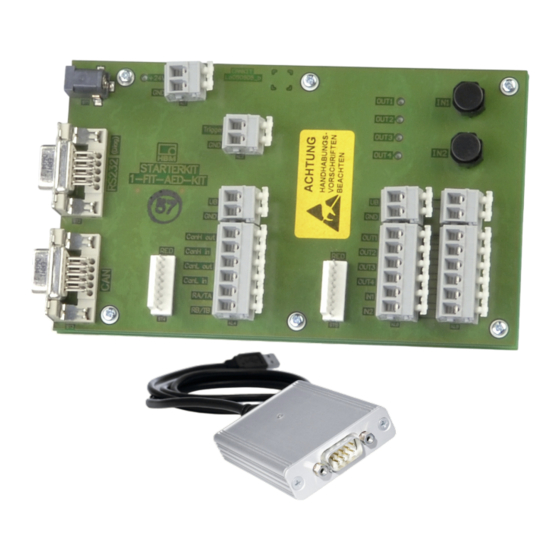
SCOPE OF SUPPLY Starter Kit PCB Power supply (input 100 … 240 V , output 24 V , max. 1.25 A) PEAK-USB adapter (CAN bus to USB) Connection cable (D-sub-HD15 female and male, 9-pin) This operating manual You can use the connection cable (D-sub-HD15 9-pin) either to connect the diagnos tics bus to the PC COM port or as an extension connecting between the PEAK-USB adapter and the Starter Kit. -
Page 10: Device Default Settings
DEVICE DEFAULT SETTINGS The settings described below are defaults that you will need for initial commissioning. AED9401A or AED9501A Settings in the AED9401A basic device (see Fig. 6.1 on page 11): Select bus CANopen or DeviceNet: Switch S2 Bus terminator to on: Switch S1 Bus isolator to off: Switch S3 Settings in the AED9501A basic device (see Fig. -
Page 11: Setup For Initial Commissioning
SETUP FOR INITIAL COMMISSIONING The pin assignment of the AEDs is shown in Fig. 6.1 on page 11 and in Fig. 6.2 on page 13. That of the FIT is shown in Fig. 6.3 on page 15. For more information, refer to the AED and FIT operating manuals. -
Page 12: Aed9401A
AED9401A You can omit connections you do not need, depending on whether you want to connect to the AED via the CAN bus or the diagnostics bus. Connect only the connections you want on the Starter Kit to those on the AED according to the following schematic: Connection labeling on the Starter Kit Connection labeling on the AED (KL3, KL5 or KL7) - Page 13 Starter Kit Power supply 1-FIT-AED-KIT unit +24 V 24 V OUT1 OUT2 OUT3 Trigger OUT4 Cable COM1 (SUB-D9) OUT1 CanH out OUT2 CanH in OUT3 CanL out PEAK OUT4 CanL in adapter RA/TA RB/TB AED9401A with AD103C OUT4 OUT3 OUT2 OUT1...
-
Page 14: Aed9501A
AED9501A You can omit connections you do not need, depending on whether you want to connect to the AED via the CAN bus or the diagnostics bus. Connect only the connections you want on the Starter Kit to those on the AED according to the following schematic: Connection labeling on the Starter Kit Connection labeling on the AED (KL3, KL5 or KL7) - Page 15 Starter Kit Power supply 1-FIT-AED-KIT unit 24 V +24 V OUT1 OUT2 OUT3 Trigger OUT4 Cable COM1 (SUB-D9) OUT1 CanH out OUT2 CanH in OUT3 CanL out PEAK OUT4 CanL in adapter RA/TA RB/TB Bus terminator AED9501A with AD103C CAN Low...
-
Page 16: Fit Load Cell
FIT load cell You can omit connections you do not need, depending on whether you want to connect to the FIT via the CAN bus or the diagnostics bus. Connect only the connections you want on the Starter Kit to those of device socket 1 on the FIT. Depending on the FIT design, the connections are used either for an RS-485 interface or for CANopen or DeviceNet. - Page 17 Starter Kit Power supply 1-FIT-AED-KIT unit 24 V +24 V OUT1 OUT2 OUT3 Trigger OUT4 Cable COM1 (SUB-D9) OUT1 CanH out OUT2 CanH in OUT3 CanL out PEAK OUT4 CanL in adapter RA/TA RB/TB FIT load cell Fig. 6.3 Connecting the FIT load cell to the Starter Kit (schematic) ®...
-
Page 18: Initial Commissioning
INITIAL COMMISSIONING If you have not already done so, download the PanelX program from the HBM website's Weighing Technology section: https://www.hbm.com/AED. Then install the program on your PC. Follow the procedure below to set up the devices: Connect a transducer to the AED9401A or AED9501A. Connect the AED or FIT load cell to the starter KIT. - Page 19 Fig. 7.1 Accessing the Scan dialog Fig. 7.2 Selecting the bus system and baud rate ® -AED-Kit INITIAL COMMISSIONING...
- Page 20 Fig. 7.3 Home menu with device information based on the example of FIT ® -AED-Kit INITIAL COMMISSIONING...
-
Page 21: Technical Support
TECHNICAL SUPPORT If you have any problems while working with the AED or FIT load cell, you can use the following services: E-mail support support@hbkworld.com Telephone support Telephone support is available on all working days from 09:00 to 5:00 PM (CET/CEST): +49 6151 803-0 The following options are also available: HBM Support and Sales International: https://www.hbm.com/en/0051/worldwide-contacts/. -
Page 22: Maintenance
MAINTENANCE The Starter Kit is maintenance-free. Cleaning Disconnect the Starter Kit from all current and voltage supplies. Never use solvents, as they may corrode the label. When cleaning, ensure that no liquid gets into the connections. ® -AED-Kit MAINTENANCE... -
Page 23: Disposal And Environmental Protection
DISPOSAL AND ENVIRONMENTAL PROTECTION All electrical and electronic products must be disposed of as hazardous waste. The correct disposal of old equipment prevents ecological damage and health hazards. The Starter Kit must not be disposed of in household waste. As waste disposal regulations differ from country to country, please contact your local authority or HBM representative as necessary. - Page 25 ENGLISH DEUTSCH Bedienungsanleitung ® -AED-Kit...
- Page 26 INHALTSVERZEICHNIS Sicherheitshinweise ..........Verwendete Kennzeichnungen .
-
Page 27: Sicherheitshinweise
SICHERHEITSHINWEISE Bestimmungsgemäße Verwendung ® Der Starter‐Kit darf ausschließlich für die Ersteinrichtung der FIT -Wägezellen oder der AED9401A/AED9501A verwendet werden. Jeder darüber hinausgehende Gebrauch gilt als nicht bestimmungsgemäß. Jede Person, die mit Inbetriebnahme oder Betrieb des Kits beauftragt ist, muss die Bedienungsanleitung und insbesondere die sicherheitstechnischen Hinweise gelesen und verstanden haben. - Page 28 Qualifiziertes Personal Qualifizierte Personen sind Personen, die mit Aufstellung, Montage, Inbetriebsetzung und Betrieb des Produktes vertraut sind und über die ihrer Tätigkeit entsprechende Qualifikationen verfügen. Dazu zählen Personen, die mindestens eine der drei folgenden Voraussetzungen erfül len: Ihnen sind die Sicherheitskonzepte der Mess‐ und Automatisierungstechnik bekannt und sie sind als Projektpersonal damit vertraut.
-
Page 29: Verwendete Kennzeichnungen
VERWENDETE KENNZEICHNUNGEN Wichtige Hinweise für Ihre Sicherheit sind besonders gekennzeichnet. Beachten Sie diese Hinweise unbedingt, um Unfälle und Sachschäden zu vermeiden. Symbol Bedeutung Diese Kennzeichnung weist auf eine Situation hin, Hinweis die – wenn die Sicherheitsbestimmungen nicht beachtet werden – Sachschäden zur Folge haben kann. -
Page 30: Überblick
ÜBERBLICK Der Starter‐Kit dient dem Anschluss der AED9401A oder AED9501A, beide mit AD103C, ® oder der FIT -Wägezellen über CANopen oder DeviceNet an einen PC. Der Starter‐KIT stellt die elektrische Verbindung zum PC her und ermöglicht Ihnen, die Funktion von Ein- und Ausgängen zu testen. -
Page 31: Lieferumfang
LIEFERUMFANG Leiterplatte Starter‐Kit Netzteil (Eingang 100 … 240 V , Ausgang 24 V , max. 1,25 A) PEAK‐USB‐Adapter (CAN-Bus auf USB) Verbindungskabel (D-Sub-Buchse und D-Sub-Stecker, 9-polig) Diese Bedienungsanleitung Sie können das Verbindungskabel (D-Sub 9-polig) entweder für den Anschluss des Diagnose‐Busses an den PC‐COM‐Port oder als Verbindungskabel (Verlängerung) zwischen PEAK‐USB‐Adapter und Starter‐Kit verwenden. -
Page 32: Grundeinstellungen Der Geräte
GRUNDEINSTELLUNGEN DER GERÄTE Die im folgenden beschriebenen Einstellungen sind Grundeinstellungen, die Sie zur Inbetriebnahme benötigen. AED9401A oder AED9501A Einstellungen im Grundgerät AED9401A (siehe Abb. 6.1 auf Seite 11): Bus CANopen oder DeviceNet wählen: Schalter S2 Busabschluss auf on: Schalter S1 Bustrennung auf off: Schalter S3 Einstellungen im Grundgerät AED9501A (siehe Abb. -
Page 33: Aufbau Für Die Inbetriebnahme
AUFBAU FÜR DIE INBETRIEBNAHME Die Anschlussbelegung der AEDs ist in Abb. 6.1 auf Seite 11 sowie in Abb. 6.2 auf Seite 13, die der FIT in Abb. 6.3 auf Seite 15 dargestellt. Weitere Informationen finden Sie in den jeweiligen Bedienungsanleitungen von AED und FIT. Um die Geräte in Betrieb zu nehmen, müssen Sie diese mit dem Starter-Kit verbinden. -
Page 34: Aed9401A
AED9401A Je nachdem, ob Sie sich über den CAN-Bus oder den Diagnose-Bus mit der AED ver binden möchten, können Sie die nicht benötigten Anschlüsse weglassen. Verbinden Sie nur die von Ihnen gewünschten Anschlüsse des Starter-Kits mit denen der AED nach folgendem Schema: Anschlussbezeichnung am Starter-Kit Anschlussbezeichnung an der AED... - Page 35 Starter-Kit 1-FIT-AED-KIT Netzteil 24 V +24V OUT1 OUT2 OUT3 Trigger OUT4 Kabel COM1 (SUB-D9) OUT1 CanH out OUT2 CanH in OUT3 CanL out PEAK- OUT4 CanL in Adapter RA/TA RB/TB AED9401A mit AD103C OUT4 OUT3 OUT2 OUT1 Busauswahl DeviceNet RB/TB...
-
Page 36: Aed9501A
AED9501A Je nachdem, ob Sie sich über den CAN-Bus oder den Diagnose-Bus mit der AED ver binden möchten, können Sie die nicht benötigten Anschlüsse weglassen. Verbinden Sie nur die von Ihnen gewünschten Anschlüsse des Starter-Kits mit denen der AED nach folgendem Schema: Anschlussbezeichnung am Starter-Kit Anschlussbezeichnung an der AED... - Page 37 Starter-Kit 1-FIT-AED-KIT Netzteil 24 V +24V OUT1 OUT2 OUT3 Trigger OUT4 Kabel COM1 (SUB-D9) OUT1 CanH out OUT2 CanH in OUT3 CanL out PEAK- OUT4 CanL in Adapter RA/TA RB/TB Busabschluss AED9501A mit AD103C CAN Low CAN High T/RA Busauswahl...
-
Page 38: Fit-Wägezelle
FIT-Wägezelle Je nachdem, ob Sie sich über den CAN-Bus oder den Diagnose-Bus mit der FIT ver binden möchten, können Sie die nicht benötigten Anschlüsse weglassen. Verbinden Sie nur die von Ihnen gewünschten Anschlüsse des Starter-Kits mit denen der Geräte buchse 1 der FIT. Je nach Ausführung der FIT werden die Anschlüsse entweder für eine RS-485-Schnittstelle oder für CANopen bzw. - Page 39 Starter-Kit 1-FIT-AED-KIT Netzteil 24 V +24V OUT1 OUT2 OUT3 Trigger OUT4 Kabel COM1 (SUB-D9) OUT1 CanH out OUT2 CanH in OUT3 CanL out PEAK- OUT4 CanL in Adapter RA/TA RB/TB FIT-Wägezelle Abb. 6.3 Anschluss der FIT-Wägezelle an den Starter‐Kit (Prinzip) ®...
-
Page 40: Inbetriebnahme
INBETRIEBNAHME Falls noch nicht erfolgt, laden Sie das Programm PanelX von der Website von HBM und den Bereich Wägetechnik herunter: https://www.hbm.com/AED. Installieren Sie dann das Programm auf Ihrem PC. Gehen Sie wie im Folgenden beschrieben vor, um die Geräte einzustellen: Schließen Sie einen Aufnehmer an die AED9401A oder AED9501A an. - Page 41 Abb. 7.1 Scan-Dialog aufrufen Abb. 7.2 Auswahl des Bussystems und der Baudrate ® -AED-Kit INBETRIEBNAHME...
- Page 42 Abb. 7.3 Home-Menü mit Geräteinformationen am Beispiel FIT ® -AED-Kit INBETRIEBNAHME...
-
Page 43: Technischer Support
TECHNISCHER SUPPORT Sollten bei der Arbeit mit der AED oder FIT-Wägezelle Probleme auftreten, können Sie folgende Dienste nutzen: E-Mail-Unterstützung support@hbkworld.com Telefon-Unterstützung Die telefonische Unterstützung ist von 9:00 bis 17:00 Uhr (MEZ bzw. MESZ) an allen Werktagen verfügbar: +49 6151 803-0 Folgende Möglichkeiten stehen Ihnen ebenfalls zur Verfügung: HBM-Support und Vertrieb weltweit: https://www.hbm.com/en/0051/worldwide-contacts/. -
Page 44: Wartung
WARTUNG Der Starter-Kit ist wartungsfrei. Reinigung Trennen Sie den Starter-Kit von allen Strom‐ bzw. Spannungsversorgungen. Verwenden Sie auf keinen Fall Lösungsmittel, da diese die Beschriftung angreifen könnten. Achten Sie beim Reinigen darauf, dass keine Flüssigkeit in die Anschlüsse gelangt. ® -AED-Kit WARTUNG... -
Page 45: Entsorgung Und Umweltschutz
ENTSORGUNG UND UMWELTSCHUTZ Alle elektrischen und elektronischen Produkte müssen als Sondermüll entsorgt wer den. Die ordnungsgemäße Entsorgung von Altgeräten beugt Umweltschäden und Ge sundheitsgefahren vor. Der Starter-Kit darf nicht im Hausmüll entsorgt werden. Da die genauen Entsorgungs vorschriften von Land zu Land unterschiedlich sind, bitten wir Sie, sich im Bedarfsfall an die örtlichen Behörden oder an die betreffende HBM-Vertretung zu wenden. - Page 46 ® -AED-Kit ENTSORGUNG UND UMWELTSCHUTZ...
- Page 48 HBK - Hottinger Brüel & Kjaer www.hbkworld.com info@hbkworld.com...
Need help?
Do you have a question about the FIT-AED-Kit and is the answer not in the manual?
Questions and answers