Table of Contents
Advertisement
Quick Links
Advertisement
Table of Contents

Related Manuals for HBK FUSION


Summary of Contents for HBK FUSION
- Page 1 USER MANUAL Version 2022.0 BN2622-12...
- Page 2 Content is subject to change without notice – contact HBK for the latest version of this document. HBK ADVANTAGE, HBK FUSION, HBK COMPANION and all other trademarks, service marks, trade names, logos and product names are the property of Hottinger Brüel &...
-
Page 3: Table Of Contents
Install HBK ADVANTAGE Start the software Discover your hardware in HBK ADVANTAGE Reading the Devices explorer (Optional) Import channel setup to HBK ADVANTAGE Configure your hardware Set up the hardware Set up with HBK ADVANTAGE Optional: Set up with HBK COMPANION... - Page 4 Configure a CCLD board (B301D-12) Configure sensor parameters in HBK ADVANTAGE When the sensor is a bridge When the sensor is a resistance thermometer When the sensor is voltage When the sensor is a potentiometer When the sensor is a CCLD transducer...
- Page 5 Edit fan settings Fan modes of operation Reset the device Maintenance and care Qualified maintenance personnel Replacing air filters Cleaning Transportation, storage and disposal Diagnostics and troubleshooting Device troubleshooting Network troubleshooting Diagnostics in HBK ADVANTAGE System monitor Event log Glossary...
-
Page 7: About Hbk Fusion
About HBK FUSION ABOUT HBK FUSION HBK introduces a new era of data acquisition hardware with the HBK FUSION system of frames and boards. With universal inputs, scalable channel number, time-synchronised data and more, you gain high efficiency, high performance and reliability, and reduce the time to results. -
Page 8: Release Info
About the system The HBK FUSION modular system allows the test equipment to easily grow with your testing needs. Start with a single board in a frame, then add up to 15 more boards to expand your channel count. Add more frames and boards as needed. -
Page 9: The Software
Optional mobile app The HBK COMPANION app enables you to set up a project ahead of testing by scanning devices and sensors and identifying measurement positions and channel configurations. By importing the setup in HBK ADVANTAGE, sensor and channel configuration is automated. Thanks to the synchronization between HBK COMPANION and HBK ADVANTAGE, pictures and other documentation of the setup can be automatically assigned to the sensors. -
Page 10: Barcodes
Barcodes Barcodes All hardware devices are labelled with barcodes – this includes supported HBK sensors. Many HBK sensors are shipped with datasheets that also include the sensor barcodes. Use these barcodes to: Open the product datasheet or product page on hbkworld.com Using HBK COMPANION app, scan to read device information such as serial number and type number. -
Page 11: Health And Safety Information
End of use HBK complies with the EU’s Waste Electrical and Electronic Equipment (WEEE) Directive, which issues the following waste handling instructions: Waste electrical and electronic equipment or batteries may be returned to your local HBK office for disposal. -
Page 12: Safety Instructions
Safety instructions Labelling The product will be marked with this symbol when it is important that you refer to the associated danger or warning statement given in this document. This document uses this symbol when a danger or warning statement is applicable. Hazardous Voltage/Electricity. -
Page 13: Proper Use
Proper use Electrical hazards Voltages with no energy limit that exceed one of the following values are rated as dangerous according to EN 61010: AC voltage, 30 V rms value AC voltage, 42.4 V peak value DC voltage, 60 V When applying dangerous contact voltages, you must comply with all related safety requirements. Risk due to poor insulation of external circuits: only devices that comply with the requirements of IEC 61010- 1, IEC 61010-2-030 and IEC 60950 may be connected. -
Page 14: System Integration
System integration System integration If the product is integrated into a system, it is the responsibility of the system installer to keep the system safe. The scope of supply and performance of the product covers only a small area of measurement technology. Before starting up the product in a system, a project planning and risk analysis must first be implemented, taking into account all the safety aspects of measurement and automation technology so that residual dangers are minimized. -
Page 15: Declaration Of Conformity
Declaration of conformity Declaration of conformity NOTE The following is only guaranteed using accessories listed in this document. Conforms with the following national and international standards or technical specifications: The CE marking is the manufacturer's declaration that the product meets the requirements of the applicable EU directives. -
Page 16: Testing With High Emc Immunity
Testing with high EMC immunity Humidity EN/IEC 60068-2-78: Damp Heat: 5 to 95% RH (non-condensing) Mechanical Non-operating: IEC 60068-2-6: Vibration: Accel.: 19.6 m/s (2 g ); Dur.: 60 min; Freq.: 5 to 500 Hz; Dir.: 3 axes IEC 60068-2-27: Shock: Accel.: 245 m/s (25 g ); Pulse: 6 ms; Impacts: 3 (pos/neg 3 axes) Operating: IEC 60068-2-6: Vibration: Accel.: 9.8 m/s (1 g... -
Page 17: Supported Accessories
To order new or replacement items, contact your local representative. Software licensing HBK ADVANTAGE requires a valid license to run. A license grants a PC access to the software, based on the PC's host ID and type of license: Paid license: A leased license for any paid features. -
Page 18: Acquiring A License
License checks When you open HBK ADVANTAGE for the first time, you will have to configure your license. Subsequently, license checks are performed every time you open the software to ensure your license is valid and/or there are available tokens for you to use. -
Page 19: Getting Started
Getting Started GETTING STARTED The following pages will help you get up and running with your new HBK FUSION hardware. What's in the box? 1. Frame (housing) 2. Input boards 3. Blank boards 4. Power supply cable with plug 5. Ethernet cable 6. -
Page 20: Parts Overview
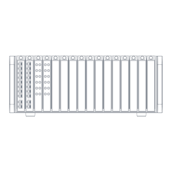
Parts overview Parts overview 1. Board fastener 2. Input connectors 3. Input connectors 4. Plastic handle cover 5. Foot for tabletop mounting 6. Fan 7. Ethernet ports: a. 1 × RJ45 (up to 2.5 Gbit/s) b. 3 × optional SFP modules for optical/copper (up to 10 Gbit/s) 8. -
Page 21: Install Hbk Fusion
HBK FUSION frames can be mounted in standard 19-inch racks. 1. Remove the handle covers. 2. Use the four cross-head screws (included) to mount the frame in the rack. Leave a space of one rack unit (1 U) below each HBK FUSION frame for air flow. - 21 -... -
Page 22: Tabletop Mounting
Tabletop mounting 3. Replace the handle covers. Tabletop mounting The two feet at the base of the front of the frame have fold-up extensions. For tabletop mounting, unfold the extensions to ensure proper air flow. - 22 -... -
Page 23: Connecting Sensors
Connect the sensor to a cable The first step in connecting sensors to the HBK FUSION hardware is to connect each sensor to the appropriate cable. The appropriate cable depends on the sensor type and board connector. See below. - Page 24 Connect the sensor to a cable Full-bridge sensors (6-wire/4-wire) Board type: B201-10 Connector type: 10 × RJ45 (each with 8 pins) Full bridges (resistive and piezoresistive) can be connected in a 6-wire or 4-wire configuration. In a 4-wire configuration, the two 'sense' lines are omitted. Both pin configurations are shown below. 6-wire configuration: Pin 1: Excitation + Pin 2: Excitation –...
- Page 25 Connect the sensor to a cable Connecting the TEDS chip: In addition, there are two ways to connect the TEDS chip: 0-wire: TEDS chip is inserted between pins 2 and 7 1-wire: TEDS chip is inserted between pins 4 and 5 EMC-immune cabling To have an EMC-immune cabling, a special wire assignment is used.
- Page 26 Connect the sensor to a cable Pin 3: Not connected Pin 4: Not connected (TEDS data) Pin 5: Not connected (TEDS ground) Pin 6: Signal + Pin 7: Not connected Pin 8: Not connected Connecting the TEDS chip: In addition, there are two ways to connect the TEDS chip: 0-wire: TEDS chip is inserted between pins 2 and 7 1-wire: TEDS chip is inserted between pins 4 and 5 EMC-immune cabling...
- Page 27 Connect the sensor to a cable Pin 1: Supply + Pin 2: Not connected Pin 3: Signal – Pin 4: Not connected (TEDS data) Pin 5: Supply ground or – Pin 6: Signal + Pin 7: Not connected Pin 8: Not connected Passive 2-wire configuration: Pin 1: Not connected Pin 2: Not connected...
- Page 28 Connect the sensor to a cable Passive 2-wire configuration with guard: Pin 1: Not connected Pin 2: Not connected Pin 3: Signal – Pin 4: Not connected (TEDS data) Pin 5: Guard Pin 6: Signal + Pin 7: Not connected Pin 8: Not connected Note that to ensure high common mode rejection, Pin 5 (guard line) needs to be connected to Sig–...
- Page 29 Connect the sensor to a cable 4-wire configuration: Pin 1: Not connected Pin 2: Excitation – Pin 3: Excitation + Pin 4: Not connected (TEDS data) Pin 5: Not connected (TEDS ground) Pin 6: Signal +/Sense + Pin 7: Sense – Pin 8: Not connected 3-wire configuration: Pin 1: Not connected...
-
Page 30: Connect The Sensor Cable To An Input Board
2. Open HBK ADVANTAGE software. 3. Go to Project > Channels in the software to check that your HBK FUSION device is detected and that the sensors have been connected correctly. All frames that are connected to the PC or LAN and each input board within that frame will show up as an available device in HBK ADVANTAGE. -
Page 31: Install Hbk Advantage
1. Double-click the application short-cut on your desktop. 2. You will need to configure your license at start-up. 3. Click Configure license. If you requested and received a free license from HBK, the software will start up immediately. You can skip all subsequent steps. - 31 -... - Page 32 4. In the dialog, To configure the license: License Manager If you have paid and received a license from HBK, click Browse to browse to the location of the license file on your PC or network. If you are connecting to a license server to check out tokens, you will also need to set up the license service under the drop-down button.
-
Page 33: Discover Your Hardware In Hbk Advantage
Discover your hardware in HBK ADVANTAGE Discover your hardware in HBK ADVANTAGE If you see the following view where there are no no available devices, then your HBK FUSION hardware is not detected. When your HBK FUSION hardware is connected to the PC or network, it is automatically detected by HBK ADVANTAGE. -
Page 34: (Optional) Import Channel Setup To Hbk Advantage
(Optional) Import channel setup to HBK ADVANTAGE It is possible to set up and modify channel properties directly in HBK ADVANTAGE, but an easier method is to import the configuration from the HBK COMPANION mobile app (requires the app is downloaded on an Android™... -
Page 35: Configure Your Hardware
16 boards locked into place in the frame. Any combination of boards is allowed. All relevant sensors connected. The frame connected to the mains and fully operational. Connection to the PC with HBK ADVANTAGE (direct or via network switch). HBK ADVANTAGE installed on a PC. Optional: HBK COMPANION app installed on an Android™... - Page 36 Set up the hardware WARNING Any empty slot must be mounted with a blank board to meet the cooling requirements of the frame. 2. Connect your sensors to the input board(s). See "Connecting sensors" on page 23 for more information. 3. Connect the frame to an AC supply. Nominal voltage input: 100 to 240 V. WARNING The frame must be positioned to allow access to the AC connector.
-
Page 37: Set Up With Hbk Advantage
LAN Set up with HBK ADVANTAGE HBK ADVANTAGE is the primary tool to set up your HBK FUSION hardware. 1. If this is the first time you are using HBK ADVANTAGE, see "Start the software"... -
Page 38: Optional: Set Up With Hbk Companion
– allowing you to prepare the multiple channels ahead of testing. The basic workflow in HBK COMPANION looks like this: 1. Import an empty channel setup file from HBK ADVANTAGE to start a project in the app. 2. Define a measuring point. -
Page 39: Using Hbk Companion
Installation is via the Google Play™ Store. Search for HBK COMPANION and tap Install. The use of barcodes in the app The barcode reader in HBK COMPANION uses the camera in your mobile device to read both 1-dimensional and 2-dimensional barcodes (a QR code is an example of a 2-dimensional barcode) . -
Page 40: Configure Channel Parameters In Hbk Advantage
Configure channel parameters in HBK ADVANTAGE Configure channel parameters in HBK ADVANTAGE Configure a bridge board (B201-10) Configure each bridge board channel with the following parameters: Channel: The channel name. This is initially derived from the device, but may be renamed. -
Page 41: Configure Sensor Parameters In Hbk Advantage
(Ω) values: 120, 350 or 1000. Connector pinning Use the diagram to confirm that the sensor pinning matches the wiring of the sensor type. Example of a 3-wire quarter bridge strain gauge as shown in HBK ADVANTAGE Figure 3-1 Characteristics For each channel, individual sensor scaling can be defined and applied. -
Page 42: When The Sensor Is A Resistance Thermometer
Wiring: The connector wiring for the selected sensor. Only 4-wire is supported. Connector pinning Use the diagram to confirm that the sensor pinning matches the wiring of the sensor type. Example of a Pt 100 resistance thermometer as shown in HBK ADVANTAGE Figure 3-2 Characteristics For each channel, individual sensor scaling can be defined and applied. -
Page 43: When The Sensor Is A Potentiometer
Wiring: The connector wiring for the selected sensor. Only 5-wire is supported. Connector pinning Use the diagram to confirm that the sensor pinning matches the wiring of the sensor type. Example of a 5-wire potentiometer as shown in HBK ADVANTAGE Figure 3-4 Characteristics For each channel, individual sensor scaling can be defined and applied. -
Page 44: When The Sensor Is A Direct Voltage Transducer
When the sensor is a direct voltage transducer Characteristics For each channel, individual sensor scaling can be defined and applied. The scaling type will determine what other parameters need to be defined. Go to "Sensor characteristics" below for information on these parameters. When the sensor is a direct voltage transducer Connector pinning Transducers are connected via a cable directly into the channel connector. - Page 45 Sensor characteristics Gain: Defines the gain between electrical input signal and scaled output signal. Gauge: Defines a linear characteristic by using the gauge factor and the bridge factor of the sensor. Two-point: Defines a linear characteristic represented by a straight line through two calibration points (x1|y1) and (x2|y2).
-
Page 46: Sample Rate
Sample rate factor: (when = Gauge) A number that expresses the strain sensitivity of the strain gauge. Gauge Scaling type (The strain sensitivity k of a strain gauge is the proportionality factor between the relative change in resistance ΔR/R0 and the strain ε to be measured: ΔR/R0 =k · ε.) Refer to the sensor data sheet to enter the correct value. - Page 47 Bridge board sample rate/filter combinations 20000 20000 1000 20000 2000 20000 50000 1000 20000 10000 2000 20000 20000 5000 20000 20000 Butterwoth IIR filter low-pass Min. Sampling Rate Cut-off Max. Sampling Rate (S/s) (Hz) (S/s) 0.01 0.02 0.05 1000 2000 2000 10000 20000...
-
Page 48: (Optional) Using Opc Ua
(Optional) Using OPC UA HBK FUSION uses the open platform communications (OPC) unified architecture (UA) protocol. The OPC UA protocol allows you to use an OPC UA client (instead of HBK ADVANTAGE) to interface with the hardware and configure its setup. You can use any OPC UA client to connect to HBK FUSION. -
Page 49: Operating Hbk Fusion
PC (direct or network connection). Set up of the hardware is also possible from any device using an OPC UA client to connect to HBK FUSION. It is the responsibility of the user to ensure the safety of any accessories used with the hardware, including any connected sensor. -
Page 50: Power
The power inlet and the protective ground connection are located at the rear of the frame. A mains power cable, which is in accordance with the destination country's standards, is shipped with HBK FUSION. The power switch is also located at the rear of the frame. Ensure the power switch is ON. -
Page 51: Direct Connection To A Pc
Direct connection to a PC Direct connection to a PC The frame can also be connected directly to the PC running HBK ADVANTAGE using the supplied LAN cable. In this case, an Internet connection is not required. It is recommended that the PC has at least 1 GHz CPU for the best performance. -
Page 52: Correct Positioning During Operation
Correct positioning during operation Correct positioning during operation Frames in a rack Rack mounting requires a 19-inch, 4U rack, with at least 1U between racks for proper air circulation. It is recommended to use a rack that is open in the front and back, to easily see the status LEDs, to connect/disconnect sensor cables and to access the power and LAN cables. -
Page 53: Calibration
PC are LAN cables and an Ethernet switch. A single Ethernet cable can transfer data and synchronize samples using PTP. HBK FUSION will work with most high-performance 1 and 2.5 Gbit network switches, but will have superior phase characteristics using a dedicated network switch with PTP support. The switch must treat IEEE 1588 packages with the same priority as data traffic. -
Page 54: Temperature Control
'Office', then the system cannot select 'Silent'. Switching boards With HBK FUSION hardware, it is possible to switch boards within a frame. This allows you to make different channel configurations for each test and to use only the hardware that is needed. -
Page 55: Removing A Board
Removing a board WARNING Any empty slot must be mounted with a blank board to meet the cooling requirements of the frame. Each board has a moveable lever. The lever locks the board in the frame and provides the force needed to connect or disconnect the board to or from the frame. -
Page 56: Inserting A Board
Inserting a board 4. For storage: Return the lever to its vertical position and lock it in place. For re-insertion: Leave the lever unlocked. Inserting a board 1. Align the board with the guide rails of the relevant slot in the frame. 2. - Page 57 Inserting a board 5. Raise the lever to its vertical position. If positioned correctly, the hook of the lever catches the fulcrum and connects the board to the backplane of the frame. 6. Lock the lever. Rotate the quarter-turn fastener clockwise. 7.
-
Page 58: Check Your Hardware
PC or on the network. When connected to he the network, any HBK ADVANTAGE user will also see these devices, but only one user can connect to a device at a time. -
Page 59: Using The Devices Explorer
Device: When a device is detected the name of the device is automatically read. This can be the default name, such as HBK-B201-serialnumber, but can also be a custom name given by a user. To change the device name, double-click the name in the table and enter text. -
Page 60: Symbols In The Table
Click at the top of the interface to expand all frames to view the boards. Availability When a device is connected directly to the PC running HBK ADVANTAGE or connected via the LAN, its status is shown as available. The following table shows status options for each connected device. -
Page 61: Firmware Version
WARNING To record data, all connected hardware must have the same firmware version. If you are connected to HBK FUSION devices with different firmware versions, you will be prompted to update all devices to the latest firmware version. HBK ADVANTAGE monitors and manages the firmware installed on all HBK FUSION devices. -
Page 62: Device Web Page
"Devices table in HBK ADVANTAGE" on page 59 of HBK ADVANTAGE The web page can be used as a supplement to HBK ADVANTAGE or in some situations as an alternative – bypassing the need for HBK ADVANTAGE to view hardware status, hardware information and perform simple maintenance tasks. -
Page 63: Functions Provided On The Device Web Page
"Reset the device" on page 66 for instructions. Update firmware HBK ADVANTAGE monitors and manages the firmware installed on all HBK FUSION devices. A warning icon in the Devices table indicates that a newer firmware version is available. - 63 -... -
Page 64: Edit Network Settings
You can update the firmware for both frames and boards: Directly in HBK ADVANTAGE: Go to Home > Devices and click Maintenance for the relevant device. Via the device web page: In a web browser, enter the device's IP address in the address bar. -
Page 65: Edit Synchronization Settings
Edit synchronization settings 6. Enter the address, for example 172.17.123.200. Gateway 7. Click Apply. Edit synchronization settings It is possible to configure the synchronization between frames. 1. In a web browser, enter the frame's IP address in the address bar. 2. -
Page 66: Fan Modes Of Operation
Fan modes of operation Fan modes of operation Silent mode Quietest mode with the fans running slowly This mode will work well for a limited time, and at normal ambient temperatures Office mode Mode where the fans are running at a slightly louder, medium speed Regarding noise, this mode would be a good compromise when used at normal office temperatures Factory mode Mode where the fans are running at a higher speed, with more cooling... -
Page 67: Maintenance And Care
Regularly check the power cable for any damages, as you would other electrical installations and equipment. Always use the power cable delivered with the product and order a new one from HBK in the case of damage. If a special length is required, contact your HBK customer service and have trained personnel connect... -
Page 68: Replacing Air Filters
6. Replace the ventilation plate and the screws which hold the plate in place. Cleaning HBK FUSION is a maintenance-free product. However, you can clean the housing with a soft, slightly damp (not wet!) cloth. Please note the following information before cleaning the housing: Disconnect the hardware completely from all current and voltage supplies. - Page 69 If the hardware has been transported at extreme temperatures, wait for at least 2 hours to allow the hardware to acclimatize before switching it on. Storage Store HBK FUSION hardware somewhere dry and enclosed. Disposal In accordance with national and local environmental protection, material recovery and recycling regulations, hardware that can no longer be used must be disposed of separately and not with normal household waste.
-
Page 70: Diagnostics And Troubleshooting
IP addresses that are not in the same range. Normally, the first three octets are the same and the fourth one varies, such as 169.254.10.252 and 169.254.10.200. Identical IP addresses. The PC and HBK FUSION device must have at least one different digit in the fourth octet. -
Page 71: System Monitor
System monitor A system monitor that allows you to view critical system parameters and PC performance including storage, power and network usage. An event log that shows: Warnings, errors and other notifications Recording status during and after data recording Each section of the page, Diagnostics Charts and Diagnostics Event Table, can be hidden ( ) and shown ( as needed. -
Page 72: Event Log
Event log NOTE The system status monitor is updated every second to provide the latest diagnostic information. Event log The event log lists the various events that occur in the system – both hardware and software. The table will include an event icon, a description, time and date. Events may include: Connection and disconnection of hardware Starting, pausing and stopping of recordings... - Page 73 Each event has its own specific description to help you identify and fix any issues quickly. All events are written into a log file, which can be shared with HBK technical support in the event of an issue. Log files are stored for 7 days.
-
Page 74: Glossary
10 Hz. The .bkc (BK Common) file format is an HBK format that saves data (time and function) with metadata and is an effective format to use when sharing data. - Page 75 Data acquisition. See Acquisition. Digital Indicator A digital representation of the measured values for a single channel. In the HBK ADVANTAGE, it is a visu- alization object to display the numerical value and physical unit of a signal. Edge Trigger A trigger that is initiated when a signal crosses, in a positive or negative direction, a set level.
- Page 76 Embedded software running on measurement electronics. Frame One type of housing within the HBK FUSION platform. A frame has standard dimensions, 19-in wide and 4 U high to fit into standard cabinets. Frames have different functions for the platform: they power, synchronize and interconnect boards incl.
- Page 77 Recording (noun) A file (or set of files) that contains the data and all associated metadata that is acquired during a recording ses- sion. In HBK ADVANTAGE, recordings are saved in .bkc format. Recording (verb) The act of collecting data for storage, playback, analysis or sharing.
- Page 78 Glossary Scaling Determines the calibration characteristic and defines how a valid range of electrical values, for example, from 0 to 10 mV/V, is mapped to the corresponding engineering values, for example, from 0 to 50 N. Sensor A device that detects or measures a physical property and records, indicates, or otherwise responds to it. A passive sensor, such as a strain gauge, is generally not able to furnish energy at its output, so a conditioning cir- cuit surrounds the sensor to create a signal (voltage, current, or both).
- Page 79 This scaling type defines a linear characteristic represented by a straight line through two calibration points. Y(t) Display Graph that shows the variation of the signal y over time. In HBK ADVANTAGE, it is a visualization object to dis- play the time series data of a signal both live and during post-processing.
- Page 80 To learn more about all HBK offerings, please visit hbkworld.com.
Need help?
Do you have a question about the FUSION and is the answer not in the manual?
Questions and answers