Table of Contents
Advertisement
Quick Links
KA01411F/00/EN/02.21
71515028
2021-01-25
Products
Brief Operating Instructions
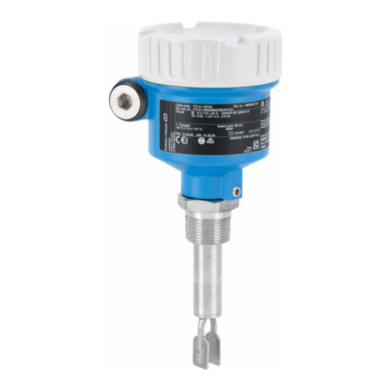
Liquiphant FTL41
Vibronic
Point level switch in liquids
These Instructions are Brief Operating Instructions; they are
not a substitute for the Operating Instructions pertaining to
the device.
Detailed information about the device can be found in the
Operating Instructions and the other documentation:
Available for all device versions via:
• Internet:
www.endress.com/deviceviewer
• Smart phone/tablet: Endress+Hauser Operations App
Solutions
Services
Advertisement
Table of Contents

Related Manuals for Endress+Hauser Liquiphant FTL41


Summary of Contents for Endress+Hauser Liquiphant FTL41
- Page 1 Operating Instructions pertaining to the device. Detailed information about the device can be found in the Operating Instructions and the other documentation: Available for all device versions via: • Internet: www.endress.com/deviceviewer • Smart phone/tablet: Endress+Hauser Operations App...
- Page 2 Liquiphant FTL41 Order code: XXXXX-XXXXXX Ser. no.: XXXXXXXXXXXX Ext. ord. cd.: XXX.XXXX.XX Serial number www.endress.com/deviceviewer Endress+Hauser Operations App A0023555 Endress+Hauser...
-
Page 3: Table Of Contents
Liquiphant FTL41 Table of contents Table of contents About this document ............. . 3 Symbols . - Page 4 About this document Liquiphant FTL41 This symbol alerts you to a dangerous situation. Failure to avoid this situation can result in minor or medium injury. NOTICE This symbol contains information on procedures and other facts which do not result in personal injury.
-
Page 5: Basic Safety Instructions
The operator is responsible for ensuring failure-free operation of the device. Modifications to the device Unauthorized modifications to the device are not permitted and can lead to unforeseeable dangers. ‣ If, despite this, modifications are required, consult with Endress+Hauser. Endress+Hauser... -
Page 6: Product Safety
(www.endress.com/deviceviewer): All the information about the measuring device and an overview of the Technical Documentation supplied are displayed. • Enter the serial number on the nameplate into the Endress+Hauser Operations App or use the Endress+Hauser Operations App to scan the 2-D matrix code (QR Code) on the... -
Page 7: Storage And Transport
Liquiphant FTL41 Incoming acceptance and product identification 3.2.1 Nameplate Order code: Ser. no.: Ext. ord. cd.: Pmax: 0.83 W PNP Dev.Rev.: A0038187 1 Nameplate specifications Trademark (Endress+Hauser) Trade name (Device name) Manufacturer' s address (Certificate holder) Production location (Assembly plant) -
Page 8: Mounting
Mounting Liquiphant FTL41 A0034846 2 How the device should be handled during transportation Mounting WARNING Loss of protection rating if the device is opened in a wet environment. ‣ Only open the device in a dry environment! Mounting instructions •... -
Page 9: Mounting Conditions
Liquiphant FTL41 Mounting Mounting conditions 4.1.1 Take switch point into consideration Typical switch points, depending on the orientation of the point level switch (water +23 °C (+73 °F)) A0037915 4 Typical switch points. Unit of measurement mm (in) Installation from above... - Page 10 Mounting Liquiphant FTL41 High viscosity NOTICE Highly viscous liquids may cause switching delays. ‣ Make sure that the liquid can run off the tuning fork easily. ‣ Deburr the socket surface. High viscosity, e.g. viscous oils: < 10 000 mPa⋅s The tuning fork must be located outside the installation socket! >...
- Page 11 Liquiphant FTL41 Mounting A0033239 7 Installation examples for a highly viscous process medium 4.1.4 Take clearance into consideration Allow sufficient space outside the tank for mounting, connection and settings involving the electronic insert. A0033236 8 Take clearance into consideration...
- Page 12 Mounting Liquiphant FTL41 4.1.5 Support the device Support the device in the event of severe dynamic load. Maximum lateral loading capacity of the pipe extensions and sensors: 75 Nm (55 lbf ft). A0031874 9 Examples of support in the event of dynamic load 4.1.6...
-
Page 13: Mounting The Measuring Device
Liquiphant FTL41 Mounting Mounting the measuring device 4.2.1 Required tools Open-ended wrench, Allen key 4.2.2 Installation Horizontal installation in vessels Align the tuning fork with the marking 316L/G1 A0039125 11 Markings to align the tuning fork Use the marking to align the tuning fork in such a way that medium can run off easily and deposit buildup is avoided. - Page 14 Mounting Liquiphant FTL41 A0034851 12 Marking and fork position Screwing in the device A0034852 13 Screwing in the device • Turn by the hex bolt only, 15 to 30 Nm (11 to 22 lbf ft) • Do not turn at the housing!
-
Page 15: Sliding Sleeves
Liquiphant FTL41 Mounting Aligning the cable entry 4 0.7 Nm A0037347 14 Housing with external locking screw The locking screw is not tightened when the device is delivered. Loosen the external locking screw (maximum 1.5 turns). Turn the housing, align the cable entry. -
Page 16: Electrical Connection
Electrical connection Liquiphant FTL41 Electrical connection Required tools Flat blade screwdriver Cover with securing screw In the case of devices for use in the hazardous area with a certain type of protection, the cover is sealed by a securing screw. -
Page 17: Connecting The Measuring Device
Liquiphant FTL41 Electrical connection Connecting the measuring device 5.4.1 3-wire DC-PNP (electronic insert FEL42) • Three-wire direct current version • Switches the load via the transistor (PNP) and separate connection, e.g. in conjunction with programmable logic controllers (PLC), DI modules as per EN 61131-2... - Page 18 Electrical connection Liquiphant FTL41 Terminal assignment 350 mA U = 10...55 V DC I max: 350 mA 55 V >0,7 >0,5 4 3 1 0.5 A A0036056 16 FEL42 terminal assignment Terminal assignment at electronic insert Terminal assignment on M12 plug...
- Page 19 Liquiphant FTL41 Electrical connection Behavior of the switch output and signaling (L–) ΔU <100 µA (L–) (L–) ΔU <100 µA (L–) <100 µA (L–) A0033508 17 FEL42 switching behavior, signaling LED MAX DIP switch for setting the MAX safety...
- Page 20 Electrical connection Liquiphant FTL41 Power consumption S < 25 VA, P < 1.3 W Connectable load Loads switched via 2 potential-free changeover contacts (DPDT) • I ≤ 6 A (Ex de 4 A), U~ ≤ AC 253 V; P~ ≤ 1 500 VA, cos φ = 1, P~ ≤ 750 VA, cos φ > 0.7 •...
- Page 21 Liquiphant FTL41 Electrical connection Terminal assignment >0,7 U = 19...55 V DC >0,5 U 19...253 V AC 0.5 A A0036057 18 Universal current connection with relay output, electronic insert FEL44 When bridged, the relay output works with NPN logic...
- Page 22 2-wire NAMUR > 2.2 mA/< 1.0 mA (electronic insert FEL48) • For connection to the isolating switch repeater as per NAMUR (IEC 60947-5-6), e.g. Nivotester FTL325N from Endress+Hauser • Signal transmission H-L edge 2.2 to 3.8 mA/0.4 to 1.0 mA as per IEC 60947-5-6 (NAMUR)
- Page 23 Liquiphant FTL41 Electrical connection Behavior output signal • OK state: Current 2.2 to 3.8 mA • Demand mode: Current 0.4 to 1.0 mA • Alarm: Current 0.4 to 1.0 mA Terminal assignment IEC 60947-5-6 8,2 V DC NAMUR – >0,7 >0,5...
- Page 24 Electrical connection Liquiphant FTL41 Behavior of the switch output and signaling 2.2...3.8 mA 0.4...1.0 mA 2.2...3.8 mA 0.4...1.0 mA < 1.0 mA A0037694 21 FEL48 switching behavior and signaling MAX DIP switch for setting the MAX safety MIN DIP switch for setting the MIN safety...
-
Page 25: Post-Connection Check
Liquiphant FTL41 Electrical connection 24/25 mm 8.0 Nm A0018023 22 Example of coupling with cable entry, electronic insert with terminals M20 coupling (with cable entry), example Maximum conductor cross-section 2.5 mm (AWG 14), ground terminal inside the housing + terminals on the electronics Maximum conductor cross-section 4.0 mm... -
Page 26: Operation Options
Operation options Liquiphant FTL41 Operation options Overview of operation options 6.1.1 Operation concept Operation with DIP switches on the electronic insert 6.1.2 Elements on the electronic insert 1 2 3 >0,7 U = 19...55 V DC >0,5 U 19...253 V AC A0039317 ... -
Page 27: Further Information
Liquiphant FTL41 Commissioning Further information Further information and the documentation currently available can be found on the Endress+Hauser website: www.endress.com → Downloads. Endress+Hauser... - Page 28 *71515028* 71515028 www.addresses.endress.com...
Need help?
Do you have a question about the Liquiphant FTL41 and is the answer not in the manual?
Questions and answers