Table of Contents
Advertisement
Quick Links
Advertisement
Table of Contents

Related Manuals for THORLABS SA201-EC


Summary of Contents for THORLABS SA201-EC
- Page 1 SA201(-EC) Spectrum Analyzer Controller Operating Manual...
-
Page 3: Table Of Contents
Spectrum Analyzer Controller Table of Contents Chapter 1 Warning Symbol Definitions ........... 1 Chapter 2 Safety ................. 2 Chapter 3 Overview................3 3.1. Parts List ............... 3 3.2. Compatible Fabry-Perot Scanning Heads ....... 4 Chapter 4 Description ................ 5 4.1. Detector Gain Adjustment ..........6 4.2. - Page 4 7.1. Output Characteristics ..........17 7.2. Trigger Characteristics ..........17 7.3. Photodiode Amplifier Characteristics ......18 7.4. Physical Features ............19 7.5. Power Supply .............. 19 Chapter 8 Regulatory ............... 20 Chapter 9 Declaration of Conformity ..........21 Chapter 10 Thorlabs Worldwide Contacts........22...
-
Page 5: Chapter 1 Warning Symbol Definitions
Spectrum Analyzer Controller Chapter 1: Warning Symbol Definitions Chapter 1 Warning Symbol Definitions Below is a list of warning symbols you may encounter in this manual or on your device. Symbol Description Direct Current Alternating Current Both Direct and Alternating Current Earth Ground Terminal Protective Conductor Terminal Frame or Chassis Terminal... -
Page 6: Chapter 2 Safety
(versus being listed in this section). DANGER! The Thorlabs Spectrum Analyzer Controller, SA201, must be powered off, unplugged from the AC input source, and disconnected from any piezo elements prior to replacing the fuse or removal of the cover. Failure to do so may cause SERIOUS INJURY to the user, since high voltages exist within the unit. -
Page 7: Chapter 3 Overview
Operating Manual • 120 VAC US Power Supply Line Cord (with the SA201) or 230 VAC Power Supply Line Cord for Europe (with the SA201-EC) • 125 mA Fuse for use at 230 VAC operation (250 mA fuse installed in unit) -
Page 8: Compatible Fabry-Perot Scanning Heads
Spectrum Analyzer Controller Chapter 3: Overview 3.2. Compatible Fabry-Perot Scanning Heads This product has been designed to be used with one of our SA200, SA210, or SA30 Series Scanning Fabry-Perot Interferometers. Below is a list of available heads. Note this list is subject to change without notice. Please visit the website for the most current information. -
Page 9: Chapter 4 Description
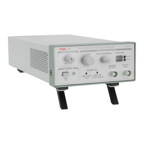
Spectrum Analyzer Controller Chapter 4: Description Chapter 4 Description Detector Gain Adjustment Waveform Control Sweep Expansion Control DC Offset Control Amplitude Control Output BNC Power On Indicator Trigger Output BNV Rise Time Control Power Switch Figure 1 SA201 Front Panel Controls Rev H, November 30, 2021 Page 5... -
Page 10: Detector Gain Adjustment
Spectrum Analyzer Controller Chapter 4: Description 4.1. Detector Gain Adjustment The SA201 includes a built in photodiode amplifier circuit. This amplifier is designed specifically to operate with the detector provided with the SA200 series Fabry-Perot Interferometer, allowing the user to monitor the transmission of the cavity. -
Page 11: Amplitude Control
Spectrum Analyzer Controller Chapter 4: Description 4.7. Amplitude Control The amplitude control allows the user to adjust the ramp amplitude from 1 to 30 V peak to peak using a 10-turn trim pot. Note, the ramp signal is added to the DC offset. -
Page 12: Trigger Output Bnc
0.6 µF piezo loads at a ramp rate of 1 ms over the full voltage range. The output current is internally limited to prevent damage to the output drive. Note: the output performance specifications assume a Thorlabs Fabry-Perot Interferometer module is connected. -
Page 13: Ground Plug
This input BNC is used to interface the photodetector, provided with the SA200 scanning heads, to the amplifier circuit. The photodiode amplifier is configured to operate with the Thorlabs supplied photodetectors; however it is possible to operate user supplied photodetectors. To do so, the BNC center contact must be connected to the photodetector cathode and the BNC shell must be connected to the photodiode anode (unbiased operation). -
Page 14: Pd Amplifier Output Bnc
Spectrum Analyzer Controller Chapter 4: Description NOTE The PDAVJ5 that is recommended for use along with the SA200-30C should not be connected to this input. Connecting to the amplifier will cause damage to the instrument. 4.14. PD Amplifier Output BNC This BNC is the amplifier output and may be connected directly to an oscilloscope to view the cavity spectrum. -
Page 15: Chapter 5 Operation
Spectrum Analyzer Controller Chapter 5: Operation Chapter 5 Operation 5.1. PD Blanking Circuit The detector amplifier includes a blanking circuit, which blocks any photodetector response during the falling edge of the saw tooth waveform. This is very useful when triggering on the photodiode spectral response, because unwanted signals while the cavity resets will be removed. -
Page 16: Replacing The Fuse
125 mA Type ’T’ Slow Blow Fuse – The 125 mA fuse is required for 230 • V operation only. Thorlabs supplies a 125 mA fuse with all of its SA201 units and must be installed when operating at 230 VAC. -
Page 17: Selecting The Line Voltage
Spectrum Analyzer Controller Chapter 5: Operation Locate the fuse box between the input line voltage connector and the transformer. Fuse with Fuse Cover On Figure 6 SA201 Fuse with Fuse Cover Remove the fuse cover and slide the old fuse out. Install the new fuse into the fuse cover and place back into the fuse box. -
Page 18: Chapter 6 Recommended Setup
Spectrum Analyzer Controller Chapter 6: Recommended Setup Chapter 6 Recommended Setup 6.1. Recommended Setup for SA200 Series Fabry-Perot Interferometers (Except SA200-30C) Figure 7 Recommended Setup Diagram (Except SA200-30C) Page 14 6679-D02... -
Page 19: Recommended Setup For Sa200-30C Fabry-Perot Interferometer
Spectrum Analyzer Controller Chapter 6: Recommended Setup 6.2. Recommended Setup SA200-30C Fabry-Perot Interferometer Figure 8 Recommended Setup Diagram for SA200-30C Rev H, November 30, 2021 Page 15... - Page 20 Spectrum Analyzer Controller Chapter 6: Recommended Setup Connection Description Controller (BNC) to Piezo (Cable is Attached to FP Interferometer) Photodiode (SMA) to Controller (BNC) (Included with FP Interferometer) Amplified Photodiode Output (BNC) to Oscilloscope (Not Included) Trigger Output of Controller (BNC) to Oscilloscope (Not Included) Optional Connection that Allows the User to Monitor the Signal used to Drive the...
-
Page 21: Chapter 7 Specifications
Spectrum Analyzer Controller Chapter 7: Specifications Chapter 7 Specifications 7.1. Output Characteristics Item # SA201 Waveforms Sawtooth / Triangle Default Waveform Saw tooth Saw tooth Fall Time 1 ms Typical Output Voltage Range 1 to 45 V (Offset + Amplitude) Max Supply Current 15 mA 26 mA Max... -
Page 22: Photodiode Amplifier Characteristics
Spectrum Analyzer Controller Chapter 7: Specifications 7.3. Photodiode Amplifier Characteristics Item # SA201 Gain Steps 0, 10, 20 dB Transimpedance Gain (Hi-Z) 10K, 100K, 1M V/A Transimpedance Gain (50 Ω) 5K, 50K, 500K V/A ±0.1% @ 10K (±0.12%) Gain Error ±0.12% @ 100K (±0.15%) ±0.14% @ 1M (±0.3%) 50 Ω... -
Page 23: Physical Features
Spectrum Analyzer Controller Chapter 7: Specifications 7.4. Physical Features Item # SA201 5.8" x 2.8" x 12.5" Dimensions (W x H x D) (147 mm x 71 mm x 317.5 mm) Input and Output BNCs Connectors Offset Control 10-Turn Potentiometer Amplitude Control 10-Turn Trim pot 10-Turn Trim pot... -
Page 24: Chapter 8 Regulatory
Waste Treatment is Your Own Responsibility If you do not return an “end of life” unit to Thorlabs, you must hand it to a company specialized in waste recovery. Do not dispose of the unit in a litter bin or at a public waste disposal site. -
Page 25: Chapter 9 Declaration Of Conformity
Spectrum Analyzer Controller Chapter 9: Declaration of Conformity Chapter 9 Declaration of Conformity Rev H, November 30, 2021 Page 21... -
Page 26: Chapter 10 Thorlabs Worldwide Contacts
Spectrum Analyzer Controller Chapter 10: Thorlabs Worldwide Contacts Chapter 10 Thorlabs Worldwide Contacts technical support sales inquiries, please visit www.thorlabs.com/contact for our most up-to-date contact information. USA, Canada, and South America UK and Ireland Thorlabs, Inc. Thorlabs Ltd. sales@thorlabs.com sales.uk@thorlabs.com techsupport@thorlabs.com... - Page 28 www.thorlabs.com...
Need help?
Do you have a question about the SA201-EC and is the answer not in the manual?
Questions and answers