
Related Manuals for THORLABS SHB1


Summary of Contents for THORLABS SHB1
- Page 1 SHB1 and SHB1T 1" High Speed Shutters and Controller User Guide Original instructions in accordance with EC-Machinery Directive 2006/42/EC...
-
Page 2: Table Of Contents
Chapter 9 Mechanical Drawing ............17 Chapter 10 Declaration of Conformity ..........18 Chapter 11 Regulatory ............... 19 Chapter 12 Thorlabs Worldwide Contacts........20 Original instructions in accordance with EC-Machinery Directive 2006/42/EC... -
Page 3: Chapter 1 Warning Symbol Definitions
Ø1" Shutters and Controller Chapter 1: Warning Symbol Definitions Chapter 1 Warning Symbol Definitions Below is a list of warning symbols you may encounter in this manual or on your device. Symbol Description Direct Current Alternating Current Both Direct and Alternating Current Earth Ground Terminal Protective Conductor Terminal Frame or Chassis Terminal... -
Page 4: Chapter 2 Safety
100 to 240 VAC. There is no need to change the fuse when selecting your regional mains voltage. There are no user serviceable parts in this product. CAUTION DO NOT OPEN HOUSING! The SHB1 and SHB1T shutters and controller have no user-serviceable parts. Do not operate without cover installed. WARNING Do not operate in wet or damp conditions. -
Page 5: Chapter 3 Description
In the event of a failure such as a blade jam, the SHB1(T) will shut down. This changes the state of the interlock and LED light will turn red. The SHB1(T) can detect when the blades are not operating at the set frequency and will shut down to prevent damage to the SHB1(T). -
Page 6: Overview
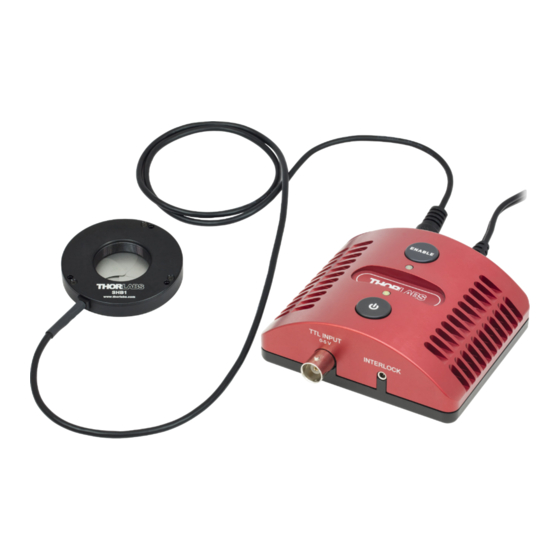
Ø1" Shutters and Controller Chapter 3: Description 3.1. Overview Enable Button Power LED Status LED Power Button Interlock Jack External Modulation Input Figure 1 Controller Front View Shutter Head DC Input Jack Jack Figure 2 Controller Rear View Page 4 21690-D02... - Page 7 Ø1" Shutters and Controller Chapter 3: Description Ø0.10" Mounting Through Holes, 3 Places Ø1.0" 5-Bladed Aperture SM1 Thread (1.035"-40) SHB1 Shutter Head, Front SHB1 Shutter Head, Rear Ø0.10" Mounting Through Holes, 3 Places Ø1.0" 5-Bladed Aperture SM1 Thread (1.035"-40) SHB1T Shutter Head, Front...
-
Page 8: Chapter 4 Setup And Operation
Connect the AC power cord to the power supply and then connect to the AC power outlet. The SHB1 and SHB1T are each supplied with an external AC-DC switching power supply rated at 100 – 240 VAC, 47 –... -
Page 9: External Modulation Modes
Manual Mode without opening the shutter and the Status LED will flash four times. The SHB1(T) is set to the last mode it was in when it is powered on. Pressing the ENABLE button puts it in Manual Mode if it was in Protected or Unprotected External Modulation Mode. -
Page 10: Protected Mode
4.3.1. Protected Mode When the SHB1(T) operates in Protected Mode, the device will shut down if run for too long over 10 Hz. This is in order to protect the device from overheating. The unit does not monitor the temperature directly, but the time limit is based on calculations assuming no heat control at room temperature. -
Page 11: Default To On
4.4. Default to On The default to on setting allows the SHB1(T) to automatically power ON when DC is applied; for users that require auto power ON when DC is applied without pressing the POWER button. To enter or exit this setting, follow the steps below: Connect the DC power supply. -
Page 12: Indicators
Ø1" Shutters and Controller Chapter 4: Setup and Operation 4.6. Indicators 4.6.1. Power LED The Power LED will be lit green when the power is on and dark when the power is off. 4.6.2. Status LED The table below outlines the color of the Status LED and the meaning depending on the mode. -
Page 13: Timing Performance
Chapter 4: Setup and Operation 4.7. Timing Performance External Modulation Input Pulse Open Shutter Response Close Figure 5 SHB1(T) Timing Driven by SHB1(T) Shutter Controller Time Time (ms, Typ) (ms, Max) Definitions Delay from input pulse rising edge to initiation I A of shutter opening. -
Page 14: Typical Performance
Ø1" Shutters and Controller Chapter 4: Setup and Operation 4.8. Typical Performance The time it takes to open the shutter or close the shutter (IA and DE as shown in Figure 5) are constant characteristics of the device. The time delay for both opening and closing is a result of the time it takes to energize the coils. -
Page 15: Chapter 5 Specifications
Mechanical Specifications Aperture Diameter 1.00" (25.4 mm) Boxed Weight 3 lbs (1.4 kgs) Number of Blades SHB1: Polished Stainless Steel Blade Finish SHB1T: PTFE Coated Electrical Specifications (Power Supply) AC Line Voltage, Frequency 100 – 240, 47 – 63 Hz AC Current 0.4 A... -
Page 16: Chapter 6 Interface Connector
Ø1" Shutters and Controller Chapter 6: Interface Connector Chapter 6 Interface Connector The interface connector on the SHB1(T) is a 4-pin mini-DIN shielded female connector that accepts the 4 pin mini-DIN male connector. The pin descriptions are as follows: Description... -
Page 17: Chapter 7 Cleaning And Maintenance
Chapter 7 Cleaning and Maintenance The SHB1(T) shutter and controller can be cleaned using a soft cloth. If needed, the cloth can be dampened with some isopropyl alcohol. Avoid using any solvents on or near the unit as well as water as this may cause the blades to rust. -
Page 18: Chapter 8 Troubleshooting
Check DC plug is fully inserted into the controller's DC jack labeled 5 VDC 2.4 A. Check the SHB1(T) shutter cable 4 pin mini-DIN plug Shutter does not open or has arrow facing up and is fully inserted into the close. -
Page 19: Chapter 9 Mechanical Drawing
Ø1" Shutters and Controller Chapter 9: Mechanical Drawing Chapter 9 Mechanical Drawing Ø 1.00" 0.38 " (25.4mm) 0.50 " (9.7mm) (12.6mm) 3x Ø 0.096 " Ø 2.25 " 2.4mm (57.2mm) R1.03 " (26.0mm) 0.90 " (22.8mm) 0.45 " (11.4mm) 0.57 " (14.6mm) SM1 (1.035 "... -
Page 20: Chapter 10 Declaration Of Conformity
Ø1" Shutters and Controller Chapter 10: Declaration of Conformity Chapter 10 Declaration of Conformity Page 18 21690-D02... -
Page 21: Chapter 11 Regulatory
Waste Treatment is Your Own Responsibility If you do not return an “end of life” unit to Thorlabs, you must hand it to a company specialized in waste recovery. Do not dispose of the unit in a litter bin or at a public waste disposal site. -
Page 22: Chapter 12 Thorlabs Worldwide Contacts
Ø1" Shutters and Controller Chapter 12: Thorlabs Worldwide Contacts Chapter 12 Thorlabs Worldwide Contacts For technical support or sales inquiries, please visit us at www.thorlabs.com/contact for our most up-to-date contact information. USA, Canada, and South America UK and Ireland Thorlabs, Inc. - Page 23 www.thorlabs.com...
Need help?
Do you have a question about the SHB1 and is the answer not in the manual?
Questions and answers