Table of Contents
Advertisement
Quick Links
MS2-LFR
Filter regulator
Instructions | Operating
8110552
2019-06a
[8110554]
Translation of the original instructions
1
Applicable documents
All available documents for the product è www.festo.com/pk.
Documents
Product, type
Instruction manual
Mounting bracket, MS2-WR
Tab. 1
2
Safety
2.1
Safety instructions
–
Only use the product in original status without unauthorised modifications.
–
Only use the product if it is in perfect technical condition.
–
Observe labelling on the product.
–
Take into consideration the ambient conditions at the location of use.
–
Prior to mounting, installation and maintenance work: Switch off compressed
air supply and secure it from being switched back on.
–
Observe tightening torques. Unless otherwise specified, the tolerance
is ± 20 %.
2.2
Intended use
The filter regulator is designed to regulate the pressure in the downstream string
and prepare the compressed air (dirt particles, condensate).
2.3
Training of qualified personnel
Installation, commissioning, maintenance and disassembly should only be con-
ducted by qualified personnel.
3
Additional information
–
Accessories è www.festo.com/catalogue.
–
Documents and literature è www.festo.com/sp.
4
Service
Contact your regional Festo contact person if you have technical questions
è www.festo.com.
5
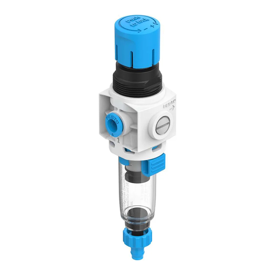
Product design
Fig. 1 Product design
Festo SE & Co. KG
Ruiter Straße 82
73734 Esslingen
Germany
+49 711 347-0
www.festo.com
8110552
Contents
Assembly
1 Rotary knob
2 Pressure gauge
3 Release button
4 Drain screw
5 Filter bowl
6 Plug screw (back)
6
Mounting
6.1
Mounting clearances
•
Maintain sufficient space around the product.
–
Space required above the product: 20 mm
–
Space required under the product: 30 mm
–
Space required left and right of the product: 30 mm
With sheet metal mounting
–
Mount product vertically
–
Observe the maximum permissible wall thickness. Wall thickness: £ 2 mm
6.2
Types of mounting
Mount product with one of the following types of mounting depending on the pur-
pose:
Type of mounting
Wall mounting with mounting bracket
Sheet metal mounting
Tab. 2 Types of mounting
6.3
Preparation
1. Observe the mounting position è 13 Technical data.
2. Note the flow direction of flow as shown by the numbers on the housing:
from 1 to 2.
3. To exhaust the system for maintenance:
Use shut-off valves in the compressed air supply line.
4. Use mounting accessories from the Festo catalogue
è www.festo.com/catalogue.
5. Note types of mounting.
6.4
Mounting the pressure gauge
1. Turn pressure gauge 2 clockwise to the stop. The pressure gauge seal is
pre-assembled on the threaded connection journal.
–
It can be converted to the Z-variant. Replace the plug screw and use the
alternative connection on the back of the device. Tightening torque: 0.5
Nm
2. Align scale. Unscrew pressure gauge anticlockwise and align the pressure
gauge scale vertically (after screwing in to stop unscrew max. 1 revolution).
6.5
Installation
1. Place product at the installation site.
2. Observe mounting clearances è 6.1 Mounting clearances.
3. Place the mounting bracket on the product.
4. Tighten mounting bracket with nut è 1 Applicable documents è Instruc-
tions, assembly.
5. Secure mounting bracket to the mounting surface.
7
Installation, pneumatic
1. Use fittings, seals and suitable hoses from the Festo catalogue
è www.festo.com/catalogue.
2. Screw fittings into the pneumatic ports.
3. Note maximum screw-in depth of the connector thread. Screwing in deeper
will reduce the flow rate. Screw-in depth: £ 6.5 mm
4. Push suitable hoses into the fitting up to the stop.
–
Position hoses axial to the pneumatic ports.
–
Hoses must not have a bending radius.
8
Setting the outlet pressure
1. Unlock rotary knob 1 (pull).
2. Turn the rotary knob completely in the z direction.
3. Exhaust system slowly: turn the rotary knob in the + direction until the
desired pressure is reached.
Maintain permissible pressure regulation range è 13 Technical data.
The inlet pressure p1 should always be at least 0.5 bar higher than the set
outlet pressure p2.
4. Lock rotary knob 1 (press).
9
Maintenance
9.1
Drain condensate manually
If the condensate reaches a level approx. 10 mm below the filter element:
1. Turn drain screw anticlockwise as seen from below.
Ä The condensate flows out.
2. Turn drain screw clockwise as seen from below.
9.2
Changing filter
Replace the filter cartridge if the flow rate is reduced even though the pressure
setting is unchanged.
1. Exhaust product with the rotary knob 1.
2. Press unlock 3 on the filter bowl.
3. Turn filter bowl 5 anticlockwise manually (as seen from below) until the stop
can be felt.
4. Pull filter bowl 5 from the housing.
5. Unscrew filter plate anticlockwise and remove used filter cartridge.
Continuing description
–
Assembly instructions
1 Applicable documents.
è
–
è
6.5 Installation.
–
6.1 Mounting clearances.
è
–
Accessories è www.festo.com/catalogue.
Advertisement
Table of Contents

Related Manuals for Festo MS2-LFR


Summary of Contents for Festo MS2-LFR
- Page 1 Observe tightening torques. Unless otherwise specified, the tolerance is ± 20 %. Installation, pneumatic Intended use 1. Use fittings, seals and suitable hoses from the Festo catalogue The filter regulator is designed to regulate the pressure in the downstream string è www.festo.com/catalogue. and prepare the compressed air (dirt particles, condensate).
- Page 2 Dispose of the packaging, used filters and product at the end of the produc- tion service life according to the valid provisions for environmentally sound recycling. Technical data 13.1 Technical data, mechanical Size MS2-LFR Mounting position [°] vertical +/– 5 Grade of filtration [µ] Condensate drain function...
Need help?
Do you have a question about the MS2-LFR and is the answer not in the manual?
Questions and answers