
Subscribe to Our Youtube Channel
Related Manuals for Festo CMMP-AS-C2-3A


Summary of Contents for Festo CMMP-AS-C2-3A
- Page 1 Motorcontroller CMMP… Description Mounting and installation Type CMMP-AS-3A… Description 557 326 en 0708NH [723 739]...
- Page 3 Edition __________________________________________________ en 0708NH Description ___________________________________ P.BE-CMMP-AS-3A-HW-EN Order no. ___________________________________________________ 557 326 (Festo AG & Co KG., D-73726 Esslingen, Federal Republic of Germany, 2006) Internet: http://www.festo.com E-mail: service_international@festo.com The reproduction of this document and disclosure to third parties and the utilisation or communication of its contents without explicit authorization is prohibited.
- Page 4 Index of revisions Author: Festo AG & Co KG Name of manual: File name: File saved at: Consec. no. Description Index of revisions Date of amendment 24.04.08 Trade names Microsoft and Windows are either registered trademarks or trademarks of Microsoft Corpo- ration in the United States and/or other countries.
-
Page 5: Table Of Contents
Intermediate circuit coupling, DC power supply ......29 3.2.3 Mains fuse .................. 29 Brake chopper ................... 29 Communication interfaces ................30 3.4.1 Festo profile for handling and positioning (FHPP) ......30 3.4.2 RS232 interface ................31 3.4.3 CAN bus ..................31 3.4.4 Profibus .................. - Page 6 Device view ....................61 Assembly ....................64 Electrical installation .................. 65 Connector pin assignments ................ 65 Entire CMMP-AS system ................66 Connection: Power supply [X9] ..............68 7.3.1 Layout on device [X9] ..............68 7.3.2 Counterplug [X9] ................68 Festo P.BE-CMMP-AS-3A-HW-EN 0708NH...
- Page 7 Layout on device [X4] ..............78 7.11.2 Counterplug [X4] ................79 7.11.3 Pin assignments [X4] ..............79 7.11.4 Connection notes [X4] ..............79 7.12 Connection: RS232/COM [X5] ..............80 7.12.1 Layout on device [X5] ..............80 7.12.2 Counterplug [X5] ................80 Festo P.BE-CMMP-AS-3A-HW-EN 0708NH...
- Page 8 Technical specifications ................101 Operation and display components ............102 Power supply [X9] ..................102 Motor connection [X6] ................104 Angle encoder connections [X2A] and [X2B] ..........104 A.4.1 Resolver connection [X2A] ............104 A.4.2 Encoder connection [X2B]............105 Festo P.BE-CMMP-AS-3A-HW-EN 0708NH...
- Page 9 Communication interfaces ................ 106 A.5.1 RS232 [X5] ................106 A.5.2 CAN bus [X4]................106 A.5.3 I/O interface [X1] ............... 107 A.5.4 Increment encoder input [X10] ........... 108 A.5.5 Incremental encoder output [X11] ..........108 Glossary ....................109 Festo P.BE-CMMP-AS-3A-HW-EN 0708NH...
-
Page 10: General Data
DeviceNet manual: P.BE-CMMP-FHPP-DN-SW Describes the implemented DeviceNet protocol. FHPP manual: P.BE-CMM-FHPP-SW Describes the implemented FHPP data profile. The entire software functionality of the new CMMP-AS series of devices has been imple- mented in a stepwise development process. Festo P.BE-CMMP-AS-3A-HW-EN 0708NH... -
Page 11: Scope Of Delivery
Inserted plug for motor connection and power Table 1.1 Scope of delivery Counterplugs for control or shaft encoder connections are not in- cluded in the standard scope of delivery. However, they can be or- dered as accessories. Festo P.BE-CMMP-AS-3A-HW-EN 0708NH... -
Page 12: Safety Instructions For Electric Drives And Controllers
The safety instructions contain reference to dangerous voltages which may occur. General information Festo AG & Co.KG is not liable for damage caused by failure to observe the warning instruc- tions in these operating instructions. Note Before commissioning, the Safety instructions for electric drives and controllers from page 12 must be read, and also chapter 7.13... - Page 13 Ask them to send the documents to the person responsible for safe operation of the servo drive controller immediately. If the servo drive controller is sold, rented and/or passed on in any other way, these safety instructions must also be passed on with it. Festo P.BE-CMMP-AS-3A-HW-EN 0708NH...
-
Page 14: Danger Through Incorrect Use
Warning DANGER! Surfaces of the device housing may be hot! Danger of injury! Danger of burning! Warning DANGER! Dangerous movements! Danger of death, serious bodily injury or damage to property due to unintentional movement of the motors! Festo P.BE-CMMP-AS-3A-HW-EN 0708NH... -
Page 15: Safety Instructions
Warning The environmental conditions specified in the product docu- mentation must be observed. Safety-critical applications are not permitted if they are not explic- itly approved of by the manufacturer. Festo P.BE-CMMP-AS-3A-HW-EN 0708NH... -
Page 16: Safety Instructions For Assembly And Maintenance
For assembling and maintaining the system, the relevant DIN, VDE, EN and IEC regulations, as well as all national and local safety and accident prevention regulations must always be observed. The system manufacturer or the user is responsible for ensuring that these regu- lations are observed: Festo P.BE-CMMP-AS-3A-HW-EN 0708NH... - Page 17 (screws, nuts, wire cut- tings) fall into the servo drive controller during mounting work and subsequent operation. Make also sure that the external voltage supply of the controller (24V) is switched off. Festo P.BE-CMMP-AS-3A-HW-EN 0708NH...
-
Page 18: Protection Against Touching Electric Components
This section concerns only devices and drive components with voltages over 50 V. It is dangerous to touch components with voltages of more than 50 V, as this can cause an electric shock. When electric devices are operated, certain components in these devices are always under dangerous tension. Festo P.BE-CMMP-AS-3A-HW-EN 0708NH... - Page 19 Do not touch the electrical connection points of the components when the device is switched on. Warning Before touching electric components with voltages over 50 V, disconnect the device from the mains or voltage source. Protect the device against being switched on again. Festo P.BE-CMMP-AS-3A-HW-EN 0708NH...
-
Page 20: Protection By Low Voltage (Pelv) Against Electric Shock
Connect only voltages and current circuits which have reliable separation of dangerous voltages. Safe isolation is achieved via isolating transformers, secure optocouplers or non- mains connected battery-powered operation. 2.4.5 Protection from dangerous movements Dangerous movements can be caused by incorrect control of connected motors. There are various causes: Festo P.BE-CMMP-AS-3A-HW-EN 0708NH... -
Page 21: Protection Against Touching Hot Components
After switching devices off, leave them for 10 minutes to cool down before touching them. If you touch hot parts of the device such as the housing which con- tains the heat sink and resistors, you may burn yourself! Festo P.BE-CMMP-AS-3A-HW-EN 0708NH... -
Page 22: Protection When Handling And Assembling
Use lifting devices and tools in a correct manner. If necessary, use suitable protective equipment (e.g. protective glasses, safety shoes, safety gloves). Do not stand under hanging loads. Wipe up spilt liquids on the floor to avoid slipping. Festo P.BE-CMMP-AS-3A-HW-EN 0708NH... -
Page 23: Product Description
The active PFC stage in the device also makes it suitable for a wide operating range, with mains voltages as low as 100 VAC. However, lim- Festo P.BE-CMMP-AS-3A-HW-EN 0708NH... - Page 24 Point-to-point positioning with and without smooth transitions. Speed and angle synchronous travel with electronic gearboxes via incremental en- coder input or Fieldbus. Comprehensive operating modes for synchronisation. A wide range of homing methods. Inching mode. Teaching mode. Festo P.BE-CMMP-AS-3A-HW-EN 0708NH...
- Page 25 500 Hz. Switchable end-stage cycle frequency. Freely programmable I/O's. User-friendly parameterisation using the Festo Configuration Tool PC program. Menu-driven commissioning. Automatic motor identification. Simple connection to a higher-level controller, e.g. a PLC via the I/O level or Fieldbus.
-
Page 26: Switch-On Sequence
Time for determination of commutator position t5 < 10 ms t6 = K x 250 µs (t Depending on the quick stop deceleration ramp cycN t7 = M x 10 ms Parameterisable (Switch-off delay t braking parameter) Table 3.1 Switch-on sequence timing Festo P.BE-CMMP-AS-3A-HW-EN 0708NH... -
Page 27: Power Supply
If the CMMP-AS servo positioning controller is supplied with less than the nominal voltage of 230 VAC then, after pre-loading is completed, a power reduction for the PFC stage is calculated based on the actual intermediate circuit voltage (see chapter A.2 Power supply [X9] page 102). Festo P.BE-CMMP-AS-3A-HW-EN 0708NH... - Page 28 PFC is deactivated, the intermediate circuit behaves like a normal intermediate circuit with an upstream bridge rectifier. The intermediate circuit voltage is usually regulated to a constant average value that, under stationary load conditions, is independent of the specified effective power of the motor. Festo P.BE-CMMP-AS-3A-HW-EN 0708NH...
-
Page 29: Intermediate Circuit Coupling, Dc Power Supply
An external braking resistor must then be connected between pins BR-CH and ZK+. This braking resistor must not be rated lower than the specified minimum value (see Table A.10 page 103). The output is fused against a short-circuit in the braking resistor or the braking resistor wiring. Festo P.BE-CMMP-AS-3A-HW-EN 0708NH... -
Page 30: Communication Interfaces
3.4.1 Festo profile for handling and positioning (FHPP) Festo has developed an optimised data profile, the "Festo Handling and Positioning Profile (FHPP)", tailored to target applications for handling and positioning tasks. The FHPP enables uniform control and programming for the various field bus systems and controllers from Festo. -
Page 31: Rs232 Interface
The following profiles are available for communication via the CAN bus: CANopen protocol in accordance with DS301 with application profile DSP402 or The Festo FHPP positioning profile. The CMMP-AS series no longer supports the specific Festo-CAN protocol of the previous SEC-AC family of devices. 3.4.4 Profibus Support of PROFIBUS communication according to DP-V0. -
Page 32: Devicenet
P.BE-CMMP-FHPP-DN-SW DeviceNet manual describes the implemented DeviceNet proto- col. Festo has developed an optimised data profile, the "Festo Handling and Positioning Profile FHPP", tailored to target applications for handling and positioning tasks. The FHPP enables uniform control and programming for the various field bus systems and controllers from Festo. -
Page 33: I/O Functions And Device Control
If the digital inputs AIN1 and ANI2 are to be used as digital inputs, then a ground reference from AGND to GND24 at plug X1 pins 14 and 6 must be established. Note Connecting AGND to GND24 renders the electronics overvoltage protection inoperable. Festo P.BE-CMMP-AS-3A-HW-EN 0708NH... - Page 34 Table 3.3 Switch-on sequence timing Actual speed value : Permanent blocking of the direction of rotation by the end switch. Actual speed value : No permanent blocking of the direction of rotation by the end switch. Festo P.BE-CMMP-AS-3A-HW-EN 0708NH...
-
Page 35: Function Overview
Position control and Interpolation Trajectories calculation: Angle encoder Power - Reference position Motor 1 and 2 stage - Motorspeed precontrol - Motorcurrent precontrol Position Speed Current controller controller controller Actual value management Fig. 4.1 Control structure of the CMMP-AS Festo P.BE-CMMP-AS-3A-HW-EN 0708NH... -
Page 36: Pulse Width Modulation (Pwm)
A fixed value of 1 or RS232 interface or CANopen-Bus interface or PROFIBUS-DP interface or DeviceNet interface or SERCOS interface 2nd and 3rd values: Setting of fixed values 2 and 3 Process controller SYNC input Additional incremental encoder input [X10] Festo P.BE-CMMP-AS-3A-HW-EN 0708NH... -
Page 37: Controlled Torque Mode
(e.g.) the external incremental encoder input. The speed setpoints can be internally specified or also derived from the data of an external encoder system (speed synchronisation via [X10] for the speed regulator). Festo P.BE-CMMP-AS-3A-HW-EN 0708NH... -
Page 38: Torque-Limited Speed Control
In positioning mode, in addition to operation with speed control, a higher-level position controller is active that measures deviations between setpoint position and current posi- tion and uses this to define setpoint values for the speed controller. Festo P.BE-CMMP-AS-3A-HW-EN 0708NH... - Page 39 = N x 1 ms (t Target window reached + response delay cycIPO t4 > 500 µs (t Setup time for position selection cycP t5 > 1 ms (t Holding time for position selection cycIPO Table 4.2 Timing positioning Festo P.BE-CMMP-AS-3A-HW-EN 0708NH...
-
Page 40: 4.2.10 Synchronisation, Electrical Gearboxes
The positioning method, travel profile, acceleration and braking times, and maximum speed can be specified for every entry. All targets can be pre- parameterised. Positioning then only requires an entry to be selected and a start command Festo P.BE-CMMP-AS-3A-HW-EN 0708NH... -
Page 41: Relative Positioning
However, this is often useful in order to bring the drive to a defined position. Concatenation of relative positioning can be used to continuously position in the same direction (e.g.) for a trimming unit or conveyor (incremental dimensions). Festo P.BE-CMMP-AS-3A-HW-EN 0708NH... -
Page 42: Absolute Positioning
Since the existing digi- tal inputs are usually occupied in normal applications, the analogue inputs AIN1 and AIN2 Festo P.BE-CMMP-AS-3A-HW-EN 0708NH... -
Page 43: Positioning Sequences
The number of positions in each positioning sequence is only limited by the total number of available positions. Every position record can be used in the path program. All position records have the fol- lowing possible settings for this: Festo P.BE-CMMP-AS-3A-HW-EN 0708NH... -
Page 44: Optional Stop Input
The servo positioning controller also calculates a corresponding speed pilot control. Festo P.BE-CMMP-AS-3A-HW-EN 0708NH... -
Page 45: Time-Synchronised Multi-Axis Positioning
For example, the Sync message of a CAN bus system can be used as the "clock" signal. This allows (e.g.) multiple axes with different path lengths and travel speeds to be moved to their targets at the same time. Festo P.BE-CMMP-AS-3A-HW-EN 0708NH... -
Page 46: Functional Safety Engineering
The safety lead to a loss of the safety function must be checked by the function. machine controller at suitable inter- The loss of the safety func- vals. tion will be detected by the next check. Festo P.BE-CMMP-AS-3A-HW-EN 0708NH... - Page 47 (main power switch or mains circuit breaker). The EN 60204-1 standard describes three Stop categories that can be used for shutdowns, depending on the results of a risk analysis (see Table 5.3). Festo P.BE-CMMP-AS-3A-HW-EN 0708NH...
-
Page 48: Integrated "Safe Standstill" Function
Less cabling effort and less space required in the switching cabinet Lower cost Another advantage is the availability of the system. The integrated solution allows the intermediate circuit of the servo controller to remain charged. This means no waiting time when the system is restarted. Festo P.BE-CMMP-AS-3A-HW-EN 0708NH... - Page 49 1. switch-off path: End stage enable via [X1] (blocking of the PWM signals; the IGBT drivers no longer receive pulse patterns). Festo P.BE-CMMP-AS-3A-HW-EN 0708NH...
-
Page 50: Secure Stopping Brake Control
MOSFET that activates the holding brake (brake applied). Caution The user is responsible for the dimensioning and the reliable func- tioning of the holding brake. The functioning of the brake must be ensured via a suitable braking test. Festo P.BE-CMMP-AS-3A-HW-EN 0708NH... -
Page 51: Functional Method / Timing
5. Functional safety engineering 5.2.3 Functional method / Timing The following timing diagram illustrates the functional method of "Safe standstill" to- gether with controller enabling and the stopping brake: Festo P.BE-CMMP-AS-3A-HW-EN 0708NH... - Page 52 Fig. 5.2 "Safe standstill" timing as per EN 954-1 Category 3 Description of the timing diagram: This timing diagram is based on the example of speed regulation using the controller en- able DIN 5 at [X1]. For Fieldbus applications, the controller enable is additionally controlled Festo P.BE-CMMP-AS-3A-HW-EN 0708NH...
- Page 53 1. Before "Safe standstill" is activated (i.e. the driver supply relay "OFF" and the end stage enable "OFF"; both switch-off paths block the PWM signals), the drive should be brought to a standstill be removing the controller enable. Depending on the applica- Festo P.BE-CMMP-AS-3A-HW-EN 0708NH...
-
Page 54: Typical Applications
6. At time t13, an "H" is displayed on the 7-segment display of the servo controller to indicate a "Safe standstill". This occurs at least 30 ms after the potential-free feed- back contact closes (t13-t12). 5.2.4 Typical applications Emergency stop circuit Festo P.BE-CMMP-AS-3A-HW-EN 0708NH... - Page 55 The EMERGENCY-STOP switching device is approved for safety category 3 as per EN954-1. A higher-level control system monitors the "EMERGENCY-STOP request" and "Driver sup- ply feedback" signals and checks them for plausibility. If an error occurs the mains circuit breaker is switched off. Festo P.BE-CMMP-AS-3A-HW-EN 0708NH...
- Page 56 Connection of the motor and the optional holding brake is not shown here and can be found in chapter 7 Electrical installation. Warning DANGER! The motor brake must be designed to be capable of stopping the drive motion. Festo P.BE-CMMP-AS-3A-HW-EN 0708NH...
- Page 57 The request to bring the motor to a standstill sets the controller enable to low. The drive slows to a speed of 0 using the defined braking ramp (parameterisable using the Festo Configuration Tool™). After the ramp time has expired (including the switch-off Festo P.BE-CMMP-AS-3A-HW-EN 0708NH...
- Page 58 "End stage driver supply" signals are then switched off after a delay by the safety compo- nent. The switch-off delay must match the braking ramp time (not shown) Warning DANGER! The motor brake must be designed to be capable of stopping the drive motion. Festo P.BE-CMMP-AS-3A-HW-EN 0708NH...
-
Page 59: Mechanical Installation
With high thermal loads on the CMMP-AS servo positioning controller, a mounting clearance of more than 71 mm is recommended! Higher thermal loading requires more clearance Festo P.BE-CMMP-AS-3A-HW-EN 0708NH... - Page 60 6. Mechanical installation Fig. 6.1 Mounting clearances for the CMMP-AS servo positioning controller Festo P.BE-CMMP-AS-3A-HW-EN 0708NH...
-
Page 61: Device View
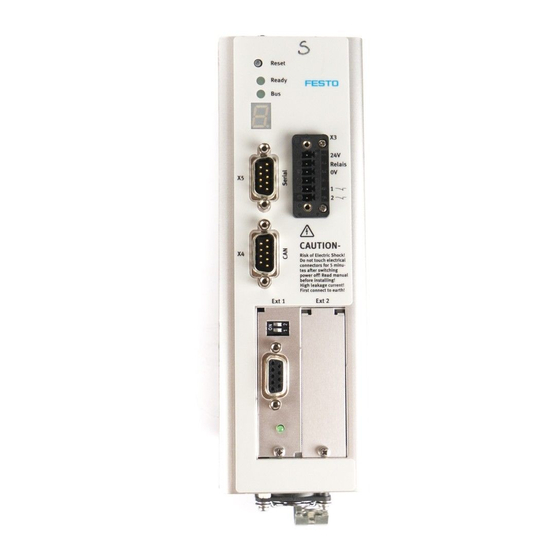
4 Slots Ext 1 and Ext 2 for the Field- bus modules 5 [X4]: Connection for the CANopen interface 6 [X5]: Connection for the RS232 serial interface 7 Status display 8 Ready LED 9 PE connection Fig. 6.2 CMMP-AS servo positioning controller: Front view Festo P.BE-CMMP-AS-3A-HW-EN 0708NH... - Page 62 6. Mechanical installation 1 [X9]: Supply 2 [X11): Incremental en- coder output 3 [X10]: Incremental en- coder input 4 [X1]: I/O communication Fig. 6.3 CMMP-AS servo positioning controller: Top view Festo P.BE-CMMP-AS-3A-HW-EN 0708NH...
- Page 63 6. Mechanical installation 1 PE connection for the outer shield of the motor cable: Spring terminal 2 [X6]: Motor connection 3 [X2A] : Resolver connection 4 [X2B]: Encoder connection Fig. 6.4 CMMP-AS servo positioning controller: Lower view Festo P.BE-CMMP-AS-3A-HW-EN 0708NH...
-
Page 64: Assembly
The clips are part of the radiator profile, ensuring an optimal heat transfer to the control cabinet plate. Please use size M4 screws to attach the servo positioning controller. Fig. 6.5 CMMP-AS servo positioning controller: Mounting plate Festo P.BE-CMMP-AS-3A-HW-EN 0708NH... -
Page 65: Electrical Installation
For operating the CMMP-AS servo positioning controller a 24 V power supply for the elec- tronics must be connected to the +24V and GND24V terminals. The power end stage supply is connected to either terminals L and N for AC supplies or to ZK+ and ZK- for DC supplies. Festo P.BE-CMMP-AS-3A-HW-EN 0708NH... -
Page 66: Entire Cmmp-As System
Main power switch Circuit breaker Fault-current circuit breaker (RCD), all-current sensitive 300 mA 24 VDC power supply CMMP-AS servo positioning controller Motor with motor and encoder cables A PC with a serial connection cable is required for parameterising. Festo P.BE-CMMP-AS-3A-HW-EN 0708NH... - Page 67 7. Electrical installation 1 Main switch 2 Circuit breaker 3 24 VDC power supply 4 External braking resistor (optional) 5 PC 6 EMMS-AS motor with encoder 7 CMMP-AS Fig. 7.2 Complete structure of CMMP-AS with motor and PC Festo P.BE-CMMP-AS-3A-HW-EN 0708NH...
-
Page 68: Connection: Power Supply [X9]
If an external braking resistor is not used, then PIN5 and PIN6 must be bridged in order for the intermediate circuit quick discharge to function! The CMMP-AS has an internal braking resistor. For higher braking power, an external resis- tor can be connected to connector [X9]. Festo P.BE-CMMP-AS-3A-HW-EN 0708NH... -
Page 69: Calculating The Required Braking Resistor
Holding brake (Motor), signal level de- pends on switching state, High side / Low 24V Brake side switch max. 1 A Cable shield for the stopping brake and the temperature sensor (not used in Festo cables) -MTdig Motor temperature sensor, NC, NO, PTC, KTY... +Mtdig +3.3 V / 5 mA... -
Page 70: Connection: I/O Communication [X1]
Fig. 7.4 shows the main functions of the digital and analogue inputs and outputs. The CMMP-AS servo positioning controller is shown to the right and the controlled connections to the left. The cable layout can also be seen. Festo P.BE-CMMP-AS-3A-HW-EN 0708NH... -
Page 71: Layout On Device [X1]
This connection removes the DIN optical isolation between GND24 and the internal GND. This makes the electronics overvoltage protection inoperative. 7.5.1 Layout on device [X1] D-SUB connector, 25-pin, female 7.5.2 Counterplug [X1] D-SUB connector, 25-pin, male Festo P.BE-CMMP-AS-3A-HW-EN 0708NH... -
Page 72: Pin Assignments [X1]
One end of the outer cable shield is connected to PE. In the CMMP-AS servo positioning controller the D-SUB connector housing is connected to PE. When using metallic D-SUB plug housings, the cable shield is simply clamped under the strain relief. Festo P.BE-CMMP-AS-3A-HW-EN 0708NH... -
Page 73: Connection Notes [X1]
An unshielded cable is often sufficient for the 24 V signals. In environments with heavy interference and with long cables (l > 2 m) between the control system and the CMMP-AS servo positioning controller, Festo recommends using shielded control cables. Despite the differential nature of the CMMP-AS servo positioning controller analog inputs, unshielded cables are not recommended for the analogue signals because the interfer- ence, e.g. -
Page 74: Connection: Safe Standstill [X3]
Connector housing Fig. 7.4 Schematic showing the main functions of the analogue inputs and outputs for cable [x1] Connection: Safe Standstill [X3] The "Safe standstill" safety function is described in chapter 5.2 Integrated "Safe stand- still" function Festo P.BE-CMMP-AS-3A-HW-EN 0708NH... -
Page 75: Layout On Device [X3]
SINE tracking signal, differential > 5 k 3.5 V /5-10 kHz COSINE tracking signal, differential > 5 k AGND Shield for signal pair (inner shield) Reference potential for temperature sensor /5-10 kHz Carrier signal for resolver 150 mA Festo P.BE-CMMP-AS-3A-HW-EN 0708NH... -
Page 76: Connection: Encoder [X2B]
Pin no. Description Value Specification +3.3 V / Ri=2 k Motor temperature sensor, NC, PTC, KTY... (not used in Festo cables) *) U_SENS+ 5 V ... 12 V / Sensor cable for the encoder supply U_SENS- 5 V/12 V/ 10%... -
Page 77: Connection: Increment Encoder Input [X10]
7.9.5 Connection notes [X10] Input [X10] can be used for processing incremental encoder signals and also for pulse direction signals as generated by stepper motor controller cards. Festo P.BE-CMMP-AS-3A-HW-EN 0708NH... -
Page 78: Connection: Incremental Encoder Output [X11]
The output driver at the signal output provides differential signals (5 V) as per the RS422 interface standard. Up to 32 other controllers can be addressed by one device. 7.11 Connection: CAN bus [X4] 7.11.1 Layout on device [X4] D-SUB connector, 9-pin, male Festo P.BE-CMMP-AS-3A-HW-EN 0708NH... -
Page 79: Counterplug [X4]
The CAN bus offers a simple, interference resistant method of networking all the compo- nents of a system together. However, this requires that all the following notes on cabling are observed. Fig. 7.5 CAN bus cabling example Festo P.BE-CMMP-AS-3A-HW-EN 0708NH... -
Page 80: Connection: Rs232/Com [X5]
8. In order to reduce the transmission of interference as much as possible, always Do not lay motor cables parallel to signal cables. The motor cables must conform to the Festo specifications. The motor cables must be correctly shielded and earthed. -
Page 81: Pin Assignments [X5]
Transmit conductor, as per RS232 specification Not assigned +RS485 Reserved for optional RS485 operation -RS485 Reserved for optional RS485 operation Interface GND, electrically connected to GND of the digital unit Table 7.10 Pin assignments of RS232 interface [X5] Festo P.BE-CMMP-AS-3A-HW-EN 0708NH... -
Page 82: Instructions On Safe And Emc-Compliant Installation
This star point must be connected to the central mass of the entire switching cabinet (short cable to mounting panel) using a cable with a large conductive area (copper strap). This connection strap is already included at the end of the Festo motor cable. With greater lengths, special EMC protective measures must be taken. -
Page 83: 7.13.4 Emc Areas: First And Second Environments
A suitable mains filter must be installed when longer cables from 25 m to 50 m are used. Interference Second environment (industrial) Regardless of motor cable length immunity Table 7.11 EMC requirements: First and second environments Festo P.BE-CMMP-AS-3A-HW-EN 0708NH... -
Page 84: 7.13.5 Emc-Compliant Wiring
7.13.6 Operation with long motor cables For applications with long motor cables and/or if the wrong motor cables are selected with excessive cable capacity, the filters may be subjected to thermal overload. In order to avoid Festo P.BE-CMMP-AS-3A-HW-EN 0708NH... -
Page 85: 7.13.7 Esd Protection
Signal transmission within the device is performed via an optocoupler. The following separate areas exist: Separate areas: Power stage with intermediate circuit and mains input Control electronics with analogue signal processing 24 V supply and digital inputs and outputs Festo P.BE-CMMP-AS-3A-HW-EN 0708NH... -
Page 86: Startup
4. Insert the motor cable plug in the corresponding socket on the motor and secure it. 5. Insert the D-SUB plug into socket [X2A] resolver or [X2B] en- coder of the device and secure the locking screws. 6. Check all plug connectors once again. Festo P.BE-CMMP-AS-3A-HW-EN 0708NH... -
Page 87: Connect The Cmmp-As Servo Positioning Controller To The Power Supply
(status display) shows a number sequence, this is an error message and you must rectify the cause of this error. If this is the case, see chapter 9.2 Error messages (page 91). If no display lights up on the device, proceed as follows: Festo P.BE-CMMP-AS-3A-HW-EN 0708NH... - Page 88 No display lights up 1. Switch of the power supply. 2. Wait 5 minutes to allow the intermediate circuit to discharge. 3. Check all connecting cables. 4. Check that the 24 V control voltage is functional. 5. Switch on the supply voltage again. Festo P.BE-CMMP-AS-3A-HW-EN 0708NH...
-
Page 89: Service Functions And Error Messages
Temperature monitoring for the heat sink The heat sink temperature of the power output stage is measured with a linear tempera- ture sensor. The temperature limit varies from device to device. A temperature warning is triggered at 5°C below the limit value. Festo P.BE-CMMP-AS-3A-HW-EN 0708NH... -
Page 90: Motor Monitoring
There is an l²t monitoring system for the PFC in the operating software. 9.1.9 Commissioning status Servo positioning controllers sent to Festo for servicing have other firmware and parame- ters loaded for testing purposes. The CMMP-AS servo positioning controller must be parameterised before it is commis- sioned again at the customer's premises. -
Page 91: 9.1.10 Operating Time Counter
E 0 1 0. Warnings have the same number as an error message. The difference is that a warning is displayed with a prefixed and suffixed hyphen, e.g. - 1 7 0 -. Festo P.BE-CMMP-AS-3A-HW-EN 0708NH... - Page 92 Internal voltage 2 failed The servo positioning controller must be sent to your local sales partner. Driver supply failure Digital I/O undervoltage Check outputs for short-circuit or check specified loading. If necessary, contact Technical Support. Digital I/O overcurrent Festo P.BE-CMMP-AS-3A-HW-EN 0708NH...
- Page 93 Unknown version of angle encoder parameter record Defective data structure in an- gle encoder parameter record Write-protected angle encoder EEPROM Angle generator EEPROM too small Overspeed (spin protection) Check parameterising of limit values. Wrong offset angle? Festo P.BE-CMMP-AS-3A-HW-EN 0708NH...
- Page 94 The parameter must be manually optimised. End stage enable could not be End stage enable was not issued, check the DIN4 issued connection. End stage was prematurely The end stage enable was switched off during identifi- switched off cation. Festo P.BE-CMMP-AS-3A-HW-EN 0708NH...
- Page 95 Send the servo positioning controller to your sales Error 1 current measurement V partner. Error 2 current measurement U Error 2 current measurement V PROFIBUS: Defective technology module? Error on initialisation Please contact Technical Support. PROFIBUS: Reserved Festo P.BE-CMMP-AS-3A-HW-EN 0708NH...
- Page 96 Technical Support. Device functionality limited! Device is not enabled for the desired functionality and may need to be enabled by Festo. The device must be sent to Festo for this. Missing user parameter record Load the default parameter record.
- Page 97 Please read the SERCOS manual and, if necessary, contact Technical Support. Negative SW limit switch The positioning setpoint has reached or exceeded the reached respective software limit switch. Check the target data. Positive SW limit switch reached Check the positioning range. Festo P.BE-CMMP-AS-3A-HW-EN 0708NH...
- Page 98 CAN: Please contact Technical Support. Too many synchronous PDOs Ethernet: User-specific (1) Please contact Technical Support. Ethernet: User-specific (2) Please contact Technical Support. 0…6 DeviceNet Fieldbus Please contact Technical Support. 0…1 DeviceNet Fieldbus Please contact Technical Support. Festo P.BE-CMMP-AS-3A-HW-EN 0708NH...
- Page 99 Please contact Technical Support. (SRAM) Missing hardware component (FLASH) FPGA boot error SD-ADUs start error SD-ADU synchronisation error after start SD-ADU not synchronous Trigger error DEBUG firmware loaded Internal initialisation error Please contact Technical Support. Table 9.2 Error messages Festo P.BE-CMMP-AS-3A-HW-EN 0708NH...
-
Page 100: Acknowledge Error
9. Service functions and error messagesTechnical specifications 9.2.3 Acknowledge error After correcting the cause of the error, the error can be acknowledged via a negative edge at input DIN5 (controller enable). Controller enable (DIN5) "No error" t1 70 ms Festo P.BE-CMMP-AS-3A-HW-EN 0708NH... -
Page 101: Technical Specifications
In accordance with EU Low Voltage Directive EMC law: Current harmonic oscillation: Further certifications Table A.3 Technical data: Ambient conditions and qualification Type CMMP-AS-C2-3A Type CMMP-AS-C5-3A Device dimensions (H*W*D) 202 x 66 x 207 mm 227 x 66 x 207 mm... -
Page 102: Operation And Display Components
CAN bus status display RESET button Hardware reset for the processor Table A.7 Display elements and RESET button Power supply [X9] Type CMMP-AS-C2-3A Type CMMP-AS-C5-3A Supply voltage 1 x 100 … 230 VAC [± 10%] Frequency 50 … 60 Hz Current consumption 3 …... - Page 103 A. Technical specifications Table A.10 Technical data: External braking resistor [X9] Type CMMP-AS-C2-3A Type CMMP-AS-C5-3A For a nominal supply voltage of 230 VAC [± 10%]: Continuous power 500 W 1,000 W Peak power 1,000 W 2,000 W Table A.11 PFC stage power data Below the nominal power supply voltage, the PFC stage power is linearly reduced.
-
Page 104: Motor Connection [X6]
A. Technical specifications Motor connection [X6] Type CMMP-AS-C2-3A Type CMMP-AS-C5-3A Data for operation with 1x 230 VAC [± 10%], 50 Hz Output voltage 0 … 270 VAC Output frequency 0 … 1,000 Hz Output power 0.5 kVA 1.0 kVA Max. output power for 5 s 1.0 kVA... -
Page 105: Encoder Connection [X2B]
Stegmann encoder: Encoders with HIPERFACE from the Stegmann company are supported in single-turn and multi-turn. The following encoder series (e.g.) can be connected: Single-turn SinCos encoders: SCS 60, SCS 70, SKS 36, SR 50, SR 60 Festo P.BE-CMMP-AS-3A-HW-EN 0708NH... -
Page 106: Communication Interfaces
Table A.16 Technical data: RS232 [X5] A.5.2 CAN bus [X4] Communication interface Values CANopen controller ISODIS 11898, Full CAN controller, max. 1M Baud CANopen protocol As per DS301 and DSP402 Table A.17 Technical data: CAN bus [X4] Festo P.BE-CMMP-AS-3A-HW-EN 0708NH... -
Page 107: I/O Interface [X1]
< 250 µs delay time AIN2 13 with an 8 V switching threshold Analogue outputs: 10 V output range, 9 bit resolution, f > 1 kHz limit AOUT0 and AOUT1 Table A.19 Technical data: Analogue inputs and outputs [X1] Festo P.BE-CMMP-AS-3A-HW-EN 0708NH... -
Page 108: Increment Encoder Input [X10]
N track can be switched off Output impedance = 66 a,diff Limit frequency > 1.8 MHz (lines/s) Limit Edge sequence Can be limited using parameters Output supply 5 V, max. 100 mA Table A.21 Technical data: Incremental encoder output [X11] Festo P.BE-CMMP-AS-3A-HW-EN 0708NH... -
Page 109: Glossary
Interference Sufficiently low interference emission of electrical, magnetic or emission electromagnetic interference of an electrical system or an electrical device on other devices in the environment via conductors and through the air. Festo P.BE-CMMP-AS-3A-HW-EN 0708NH... - Page 110 Contents ..........5 Documentation ........10 Glossary ..........110 Interference emission ....110 Interference immunity ....110 EMC ..........110 Notes General information ......12 Safety instructions ....... 15 Scope of delivery ......... 11 Setpoint sources ......... 37 Festo P.BE-CMMP-AS-3A-HW-EN 0708NH...
Need help?
Do you have a question about the CMMP-AS-C2-3A and is the answer not in the manual?
Questions and answers