
Related Manuals for Festo CMMD-AS series


Summary of Contents for Festo CMMD-AS series
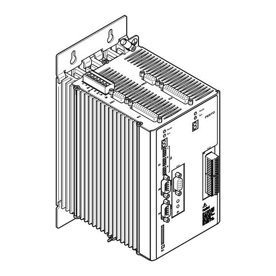
- Page 1 Motor controller Description Fitting and Installation Typ CMMD-AS-... Description 571 734 en 1002NH [751 593]...
- Page 3 Edition __________________________________________________ 1002NH en Designation ____________________________________ P.BE-CMMD-AS-HW-EN Order no. ___________________________________________________ 571 734 Festo AG & Co. KG, D-73726 Esslingen, 2010 Internet: h ttp://www.festo.com E-mail: service_international@festo.com The copying, distribution and utilisation of this document as well as the communication of its contents to others without expressed authorization is prohibited. Offenders will be held liable for compensation of damages.
- Page 4 Index of revisions Author: Festo AG & Co. KG Name of manual: Festo P.BE-CMMD-AS-HW-DE 1002NH File name: File saved at: Consec. no. Description Index of revisions Date of amendment Produced: 1002NH Trademarks ® ® ® ® ® Microsoft Windows , CANopen...
-
Page 5: Table Of Contents
RS232 interface (diagnosis/ parametrisation interface) ...... 35 3.5.6 Control via RS485 ................40 3.5.7 Multi-firmware strategy ............... 42 3.5.8 Motor feedback ..................42 3.5.9 Brake chopper (Brake control) ............. 42 3.5.10 Feedback from motor (angle encoder) ..........42 Festo P.BE-CMMD-AS-HW-EN 1002NH... - Page 6 3.5.13 SD card holder [M1] ................44 3.5.14 SD memory card .................. 44 Field bus interface ....................45 3.6.1 FHPP (Festo Handling and Positioning Profile) ........46 3.6.2 CAN bus ....................47 3.6.3 PROFIBUS .................... 48 3.6.4 DeviceNet .................... 48 Function overview ....................
- Page 7 RS232/RS485 [X5] ................109 6.4.6 Motor connection [X6.1/2]: ..............110 6.4.7 Power supply [X9] ................110 6.4.8 Synchronisation control [X10.1/2] ............. 111 6.4.9 SD card [M1] ..................111 6.4.10 Field bus settings and boot loader ............. 112 Festo P.BE-CMMD-AS-HW-EN 1002NH...
- Page 8 Operating mode and error messages ..............121 8.2.1 Operating mode and error display ............. 121 8.2.2 Error messages .................. 121 Technical data ..................... 125 General ......................125 Operation and display components ..............126 A.2.1 Status display ..................126 A.2.2 Control elements ................126 Festo P.BE-CMMD-AS-HW-EN 1002NH...
- Page 9 Shaft encoder motor [X2.1/2] ............128 A.3.3 CAN bus [X4] ..................128 A.3.4 RS232/RS485 [X5] ................128 A.3.5 Motor connection [X6.1/2] ..............129 A.3.6 Power supply [X9] ................130 A.3.7 Increment generator interface [X10.1/2] ..........130 Index ........................131 Festo P.BE-CMMD-AS-HW-EN 1002NH...
-
Page 10: General Information
1. General information General information Documentation This product manual is intended to help you safely work with the servo motor controller of the CMMD-AS series. It contains safety instructions which must be followed. This document provides information on: mechanical mounting electrical installation and an overview of the range of functions. -
Page 11: Scope Of Delivery
1. General information Scope of delivery The delivery includes: Number Delivery Servo motor controller CMMD-AS-C8-3A CD (parametrisation software, documentation, S7 module, GSD, EDS, firmware) Plug range Table 1.1 Scope of delivery Festo P.BE-CMMD-AS-HW-EN 1002NH... -
Page 12: Safety Instructions For Electric Drives And Controllers
Failure to comply can result in property damage and personal injury. Warning DANGER! Considerable property damage and personal injury can occur if these instructions are not observed. Warning Dangerous voltage The safety instructions contain reference to dangerous voltages which may occur. Accessories Environment Festo P.BE-CMMD-AS-HW-EN 1002NH... -
Page 13: General Information
2. Safety instructions for electric drives and controllers General Information Festo AG & Co.KG is not liable for damage caused by failure to observe the warning instructions in these operating instructions. Note Prior to commissioning, read through the " S afety instructions for 2 1 1 H electric drives and controllers"... -
Page 14: Hazards Due To Improper Use
Danger of death or serious bodily injury due to electric shock! Warning DANGER! High electric voltage due to incorrect connection! Danger of death or bodily injury due to electric shock! Warning DANGER! Surfaces of the device housing may be hot! Danger of injury! Danger of burning! Festo P.BE-CMMD-AS-HW-EN 1002NH... -
Page 15: Safety Instructions
Precautionary measures must be taken for preventing interference to switching systems, e.g. wiring fuses and relays with RC elements or diodes. You must observe the safety regulations and directives of the country in which the device is to be used. Festo P.BE-CMMD-AS-HW-EN 1002NH... - Page 16 EN ISO 12100 Safety of machines – basic concepts, general guidelines EN ISO 14121-1 Safety of machines – guidelines for risk evaluation EN 1037 Safety of machines – avoiding unintentional starting up EN ISO 13849-1 Safety-related parts of controllers Festo P.BE-CMMD-AS-HW-EN 1002NH...
-
Page 17: Safety Instructions For Assembly And Maintenance
(screws, nuts, pieces of wire) can fall into the motor controller. Ensure that the external power supply of the controller (mains voltage 230 V) is switched off. Festo P.BE-CMMD-AS-HW-EN 1002NH... -
Page 18: Protection Aganst Touching Electric Components
For operation, the relevant DIN, VDE, EN und IEC regulations, as well as all national and local safety and accident prevention regulations must always be observed. The system manufacturer or the user is responsible for ensuring that these regulations are observed. Festo P.BE-CMMD-AS-HW-EN 1002NH... - Page 19 Warning During installation note the amount of intermediate circuit voltage, especially with regard to insulation and protective measures. Make sure that the earthing, the cross section size of the conductor and the corresponding short-circuit protection are correct. Festo P.BE-CMMD-AS-HW-EN 1002NH...
-
Page 20: Protection By Low Voltage (Pelv) Against Electric Shock
Until the installed monitoring functions become effective, you must reckon with at least one faulty drive movement, the extent of which depends on the type of control and on the operating state. Festo P.BE-CMMD-AS-HW-EN 1002NH... -
Page 21: Protection Aganst Touching Hot Components
After switching devices off, leave them for 10 minutes to cool down before touching them. If you touch hot parts of the device such as the housing, which contains the heat sink and resistors, you may burn yourself. Festo P.BE-CMMD-AS-HW-EN 1002NH... -
Page 22: Protection When Handling And Assembling
Use lifting devices and tools in a correct manner. If necessary, use suitable protective equipment (e.g. protective glasses, safety shoes, safety gloves). Do not stand under hanging loads. Wipe up spilled liquids on the floor to avoid slipping. Festo P.BE-CMMD-AS-HW-EN 1002NH... -
Page 23: Product Description
3. Product description Product description General information The CMMD-AS series of servo positioning controllers are intelligent AC servo dual converters with extensive parametrisation possibilities and expansion options. This allows flexible use in a wide range of different applications. The servo positioning controller CMMD-AS is intended for operation of the EMMS-AS motor series with digital absolute angle encoders in single-turn and multi-turn design. -
Page 24: Bus Connection
The maximum peak current per axis is 10 A. Unlike the nominal current, a distribution of the maximum peak current is not possible. The motor nominal and peak currents are set fixed in the FCT user software. An increase in the motor nominal current can result in impermissible temperature rises. Festo P.BE-CMMD-AS-HW-EN 1002NH... - Page 25 PROFIBUS DP DeviceNet Integrated CANopen interface Open interface in accordance with CANopen Festo Handling and Positioning Profile (FHPP) Protocol in accordance with the CANopen standards DS 301 and DSP 402 Contains "Interpolated position mode" for multiple-axis applications Motion control Can be operated as a torque, speed or position controller...
- Page 26 Parametrisation program "Festo Configuration Tool FCT" Simplest start-up and diagnosis Confiuration of motor controller, motor and axis Automatic adjustment of all controller parameters with use of Festo Mechanics 2-channel oscilloscope function English and German Festo P.BE-CMMD-AS-HW-EN 1002NH...
-
Page 27: Interfaces
Start and stop functions Positioning controller Homing CANopen [X4] (CAN) Direct mode Regulating torque Chapter field bus 3.6.1 Homing Speed control (page 46) Jog mode Position control Record selection Positioning controller Interpolated Position Mode Table 3.1 Setpoint value interfaces Festo P.BE-CMMD-AS-HW-EN 1002NH... -
Page 28: Analogue Setpoint Specification
If the motor controller works as master, it can provide (RS422) A/B signals to the increment generator output (X10). When the motor controller is to operate as a slave, various inputs and signal forms are available for synchronisation. [X10] (5 V RS422) A/B, CW/CCW, CLK/DIR [X1] (24 V) CW/CCW, CLK/DIR) Festo P.BE-CMMD-AS-HW-EN 1002NH... - Page 29 CW/CCW – pulse 24V DC pulse-direction signals are carried out via [X1] DIN2 and DIN3. Clock frequency of pulse-direction signals Voltage Input Cycle rate [X10] 150 kHz up to 20 kHz 24 V [X1] Table 3.2 Maximum input frequency Festo P.BE-CMMD-AS-HW-EN 1002NH...
- Page 30 To ensure flexibility of the controller, synchronization should be switched on over the I/O interface. Required I/O activation during synchronisation via FCT DIN4 Output stage enable DIN5 Controller enable DIN6 Limit switch 0 DIN7 Limit switch 1 Festo P.BE-CMMD-AS-HW-EN 1002NH...
- Page 31 Required I/O triggering during synchronisation via mode switchover with 24 VDC frequency signals 14530d_1 The connection plan shows the switch position in the active operating state. *) The limit switches are set by default to N/C contact (configuration over FCT) Festo P.BE-CMMD-AS-HW-EN 1002NH...
- Page 32 Required I/O triggering during synchronisation via mode switchover with 5 VDC frequency signals 14531d_1 The connection plan shows the switch position in the active operating state. *) The limit switches are set by default to N/C contact (configuration over FCT) Festo P.BE-CMMD-AS-HW-EN 1002NH...
- Page 33 "running" master and the drive first has to be accelerated, the "Position synchronous" message first goes off until the position difference has been closed. Note The acknowledgment of Dout2 is firmly preset to "Position synchronous". Festo P.BE-CMMD-AS-HW-EN 1002NH...
-
Page 34: I/O Functions And Device Control
Through the CAMC-8E8A option card, additional parametrisable outputs can be added to the digital outputs available in the basic unit. Can be plugged into the technology slot Ext1 and Ext2. Depending on the option card, 8 additional outputs for status signals are available. Festo P.BE-CMMD-AS-HW-EN 1002NH... -
Page 35: Rs232 Interface (Diagnosis/ Parametrisation Interface)
In accordance with RS232 specification or RS485 specification Baud rate 9600 baud to 115 kBaud ESD protection ESD-protected (16 kV) driver Connection Null modem standard [X5] Connector socket over [X5] / D-Sub 9 pin / pin Table 3.4 Parameters of the RS232 interface Festo P.BE-CMMD-AS-HW-EN 1002NH... - Page 36 ERROR! Read the version number of the CM (Configuration VERSION? 2300:VERSION:MMMM.SSSS*) Management) release of the firmware *)MMMM: Main version of the CM release (hexadecimal format) SSSS: Subversion of the CM release (hexadecimal format) Table 3.7 General commands Festo P.BE-CMMD-AS-HW-EN 1002NH...
- Page 37 Data are greater than the upper limit, the data were limited to the upper limit 0x0000 0005 and then accepted 0x0000 0008 Data are outside the valid value range and were not written Data are currently outside the valid value range and were not written 0x0000 0009 Table 3.9 Return values Festo P.BE-CMMD-AS-HW-EN 1002NH...
- Page 38 DINs + CAN. Command: =651010:0002 As a result, the release can be granted via the CAN control word (COB 60040_00). =604000:0006 Command "Shutdown" Command: =604000:0007 Command "Switch on / Disable Operation" Command: =604000:000F Command "Enable Operation" Command: Festo P.BE-CMMD-AS-HW-EN 1002NH...
- Page 39 Start absolute positioning or Command: =604000:001F Start relative positioning Command: =604000:005F 5. After positioning has been ended, the condition of the controller is reset so a new positioning can be started. Bring motor controller into "Ready" status Command: =604000:000F Festo P.BE-CMMD-AS-HW-EN 1002NH...
-
Page 40: Control Via Rs485
For configuration, the following settings are required in the "Work station" window: On the "Application Data" page in the "Operating Mode Settings" tab, set the control interface to "RS485". On the page "Controller, Control Interface, Digital I/O", do not activate the "active" mode selection Festo P.BE-CMMD-AS-HW-EN 1002NH... - Page 41 RS232; see chapter "RS232 interface (diagnosis/ parametrisation interface)" (page 35). If required, the node number is simply written in front of the command. The node number is set via the DIP switches. Target position 10 revolutions send to Command: XT07:=607100:000A0000 node 7 Festo P.BE-CMMD-AS-HW-EN 1002NH...
-
Page 42: Multi-Firmware Strategy
3-phase synchronous motor and as an actual-value recorder for the built-in speed and position controller. The controller supports the following encoders: EnDat 2.1 encoder – exclusively digital angle information EnDat 2.2 encoder – digital angle information and service parameters (temperature) Festo P.BE-CMMD-AS-HW-EN 1002NH... -
Page 43: Control Interface [X1]
Table 6.2 Pin allocation: I/O interface [X1] mode 0 Table 6.3 Pin allocation: I/O interface [X1] mode 1 Table 6.4 Pin allocation: I/O interface [X1] mode 2 Table 6.5 Pin allocation: I/O interface [X1] mode 3. Festo P.BE-CMMD-AS-HW-EN 1002NH... -
Page 44: Increment Generator Interface [X10]
When a parameter set is loaded from the memory card, the newest parameter set is always loaded. Also, a configuration word in the parameter record can be used to specify whether firmware and/or a parameter record is to be loaded from the memory card automatically on activation. Festo P.BE-CMMD-AS-HW-EN 1002NH... -
Page 45: Field Bus Interface
Card modules may only be mounted in the slot [Ext 1]. For all field busses, the Festo Profile for Handling and Positioning (FHPP) has been implemented as the communication protocol. Additionally, for the CAN bus, the... -
Page 46: Fhpp (Festo Handling And Positioning Profile)
*) The limit switches are set by default to N/C contact (configuration over FCT) 3.6.1 FHPP (Festo Handling and Positioning Profile) FHPP makes it possible to achieve a uniform control concept regardless of the fieldbus used. The user therefore no longer has to be concerned with the specific characteristics of the respective busses or controllers (PLC), but receives a preparametrised profile in order to place his drive into operation in the shortest possible time and control it. -
Page 47: Can Bus
If the time slot pattern of the position setpoints is greater than the internal position controller cycle time of the motor controller, the controller automatically interpolates the data values between two prescribed position setpoints. The motor controller also calculates a corresponding speed pilot control. Festo P.BE-CMMD-AS-HW-EN 1002NH... -
Page 48: Profibus
In a DeviceNet network, only the bus address specified on the DIP switches is assigned. The data for the two controllers is sent in a shared telegram. Baud rates up to 500 kBaud are supported. FHPP is used as communication protocol with the control and operating modes described in chapter 3.6.1. Festo P.BE-CMMD-AS-HW-EN 1002NH... -
Page 49: Function Overview
Direct mode Positioning controller – Record selection Fieldbus Direct mode Fieldbus Record selection Homing Record selection Fieldbus Direct mode Fieldbus Record selection Jog mode – Fieldbus Direct mode Teach-in function via I/O – Table 3.14 Operating modes Festo P.BE-CMMD-AS-HW-EN 1002NH... -
Page 50: Setpoint Value Processing
The speed setpoint (without the auxiliary setpoint) is reached via a setpoint ramp. It permits setting various accelerations and brake decelerations in both directions so the resulting setpoint value process can be adjusted to the path dynamics of motor and load. The setpoint ramp can be deactivated. Festo P.BE-CMMD-AS-HW-EN 1002NH... -
Page 51: I²T Function
The parameter sets can be called up as follows: over digital inputs (position record 0 ... 63 per axis) over the RS232 interface (for test purposes only) or over a fieldbus interface. Festo P.BE-CMMD-AS-HW-EN 1002NH... - Page 52 3. Product description Required I/O interface for positioning 14532d_1 The connection plan shows the switch position in the active operating state. *) The limit switches are set by default to N/C contact (configuration over FCT) Festo P.BE-CMMD-AS-HW-EN 1002NH...
-
Page 53: Homing
Run at crawl speed in positive direction until the limit switch becomes inactive, then on to first index pulse. This position is saved as a reference point. If configured: Run at travel speed to axis zero point. Festo P.BE-CMMD-AS-HW-EN 1002NH... - Page 54 If configured: Run at travel speed to axis zero point. Note: If the reference system is shifted, runs to the limit switch or fixed stop are possible. The are therefore generally used for rotating axes. Table 3.16 Explanation of the homing methods Festo P.BE-CMMD-AS-HW-EN 1002NH...
- Page 55 Limit switch E0 Limit switch E1 DOUT0: READY DOUT1: MC DOUT2: ACK DOUT3: ERROR – = 1.6 ms = x ms (dependent on ramps) Fig. 3.4 Signal sequence with start of the homing run and with positive design Festo P.BE-CMMD-AS-HW-EN 1002NH...
- Page 56 STOP Limit switch E0 Limit switch E1 DOUT0: READY DOUT1: MC DOUT2: ACK DOUT3: ERROR Drive is moving = 1.6 ms = x ms (dependent on ramps) Fig. 3.5 Signal sequence with faulty interruption (contour error, ...) Festo P.BE-CMMD-AS-HW-EN 1002NH...
-
Page 57: Trajectory Generator
After a start signal is detected, positioning is cancelled and the drive runs at a constant speed. After pre-calculation is completed, the drive runs to the new target position (interrupting). The trajectory generator sends the following messages: Target reached, (Default: digital output DOUT1 – MC) Remaining distance reached. Festo P.BE-CMMD-AS-HW-EN 1002NH... -
Page 58: I/O Sequence Control
From all except Firmware RESET / Power ON download Initialisation Error condition Initialise SD card Ready for Acknowledge error operation Load save SD card parameters Regulating torque Activate output stage Speed control Positioning controller T10 T11 Homing mode Festo P.BE-CMMD-AS-HW-EN 1002NH... - Page 59 A fault has occurred which causes the end stage to be – switched off – – – Edge controlled fault acknowledgement DIN5: 1 – 0 The error was acknowledged and no other errors are – pending. Table 3.17 I/O sequence control Festo P.BE-CMMD-AS-HW-EN 1002NH...
-
Page 60: Safety Functions, Error Messages
Holding brake Current-carrying Motor controlled DOUT0: READY Drive is moving = 1.6 ms = x ms (dependent on brake ramps) = x ms (dependent on set switch-off delay) Fig. 3.7 Behaviour when switching off controller enable Festo P.BE-CMMD-AS-HW-EN 1002NH... - Page 61 DOUT0: READY Drive is moving = 1.6 ms = x ms (dependent on brake ramps) Fig. 3.8 Behaviour when switching off end-stage enable Note The holding brake of the EMMS-AS-…- is not suitable for braking the motor. Festo P.BE-CMMD-AS-HW-EN 1002NH...
-
Page 62: 3.7.10 Oscilloscope Function
The measuring section runs at a high priority in the rule interrupt and records the measuring channels. If the trigger condition occurs, the measurement process is cancelled after a defined number of scan steps. Festo P.BE-CMMD-AS-HW-EN 1002NH... -
Page 63: 3.7.11 Jog And Teach Function I/O
(without FCT) is used, an SD card may not be plugged in or "Read from SD after restart" must be inactive; otherwise, when the controller is restarted, the old values will be read off the SD card again. Festo P.BE-CMMD-AS-HW-EN 1002NH... - Page 64 The jog and teach function is started in I/O operation through selection of mode 1. Required I/O triggering with jog/teach 14528d_1 The connection plan shows the switch position in the active operating state. *) The limit switches are set by default to N/C contact (configuration over FCT) Festo P.BE-CMMD-AS-HW-EN 1002NH...
- Page 65 3. Product description Settings in the FCT The parameters set here are valid for jogging via I/O interface and jogging via FCT. The acceleration also applies with "Single Step" over FCT. Festo P.BE-CMMD-AS-HW-EN 1002NH...
- Page 66 STOP DIN11: Jog - DIN10: Jog + DOUT0: READY DOUT1: MC DOUT2: ACK-TEACH DOUT3: ERROR Drive is moving = 1.6 ms = x ms (dependent on brake ramps) Fig. 3.10 Signal sequence with jogging positive and negative Festo P.BE-CMMD-AS-HW-EN 1002NH...
- Page 67 DOUT1: MC DOUT2: ACK-TEACH DOUT3: ERROR Drive is moving – – – – + – = 1.6 ms = x ms (dependent on brake ramps) Fig. 3.11 Signal sequence when both signals are activated simultaneously / briefly staggered Festo P.BE-CMMD-AS-HW-EN 1002NH...
-
Page 68: Position Record Linking With Positioning/Torque Control Switching
The program lines of the route program are worked off every 1,6 ms. This ensures that an output set by the route program remains set for at least 1.6 ms. Festo P.BE-CMMD-AS-HW-EN 1002NH... - Page 69 DIN10 (NEXT1) or DIN11 (NEXT2). waiting Table 3.18 Step criteria for the route program Note The time specification for STS and TIM is the time entered in the positioning profile. The time begins with execution of the position record. Festo P.BE-CMMD-AS-HW-EN 1002NH...
- Page 70 Position records containing an end speed <> 0 must NOT be used for individual records, since the end speed condition can only be reached in linkages. Activation of record linking Record linking is started in I/O operation through selection of mode 2. Festo P.BE-CMMD-AS-HW-EN 1002NH...
- Page 71 With removal of DIN9 "Mode shift", the ongoing record linking is ended. The ongoing position record is still run to the end. With removal of DIN13 "Stop", record linking is interrupted. Record linking must then be started again. Festo P.BE-CMMD-AS-HW-EN 1002NH...
- Page 72 DOUT1: MC DOUT2: ACK DOUT3: ERROR Drive is moving = 1.6 ms = x ms (dependent on positioning) Applies for positioning records with end speed = 0 Fig. 3.13 Signal sequence at the start of a sequence Festo P.BE-CMMD-AS-HW-EN 1002NH...
- Page 73 START STOP HALT Positioning record DOUT0: READY DOUT1: MC DOUT2: ACK DOUT3: ERROR Drive is moving = 1.6 ms = x ms (dependent on brake ramps) Fig. 3.15 Signal sequence with interruption and continuation through HALT input Festo P.BE-CMMD-AS-HW-EN 1002NH...
-
Page 74: 3.7.13 On-The-Fly Measurement
For relative position records, an overrun of the position counter is possible. That is, the position counter jumps from +32767 revolutions to –32768 revolutions, for example. To be able to use the Endless positioning function, the following settings must be made during configuration. Festo P.BE-CMMD-AS-HW-EN 1002NH... - Page 75 3. Product description For linear axes: For rotational axes: Festo P.BE-CMMD-AS-HW-EN 1002NH...
-
Page 76: 3.7.15 Relative Positioning Records
The function "Endless positioning" is selected by checking "Working stroke / positioning range unlimited". The selection is available for user-defined linear and rotation axes as well as rotation axes from Festo. Note Hardware limit switches can be used with unlimited axes only for homing. -
Page 77: Functional Safety Engineering
Frequent to continuous and/or the time of the exposure to hazard is long Possibility to avoid the hazard or limit the damage Possible under certain conditions Scarcely possible Fig. 4.1 Risk graph for definition of the PLr for each safety function Festo P.BE-CMMD-AS-HW-EN 1002NH... - Page 78 - 2 safety contacts no delay - 2 safety contacts relapse delayed Connection options identical to X2P Fixed or adjustable relapse delay Cancelling the time delay through Reset button Table 4.2 Overview of the safety function in accordance with EN 61800-5-2 Festo P.BE-CMMD-AS-HW-EN 1002NH...
- Page 79 Controlled shutdown through switching EMERGENCY-STOP off of the energy when a standstill has been reached. Controlled standstill without switching Not suitable for EMERGENCY OFF off of the energy. or EMERGENCY STOP Table 4.3 Stop categories Festo P.BE-CMMD-AS-HW-EN 1002NH...
-
Page 80: Integrated Function "Safe Torque Off" (Sto)
[X3.1] and [X3.2] must always be connected in a manner conforming to the documentation. If only one plug connector [X3.1] or [X3.2] is wired, when the STO is demanded, only the corresponding power output stage is securely switched off (as depicted in chapter 4.2.3 "Switching example STO"). Festo P.BE-CMMD-AS-HW-EN 1002NH... -
Page 81: Timing Diagram, Sto
(controlled by µP) “ON” “OFF” Releasing motor holding brake (X6.Y.1/2) released (24V) Delay until brake is released! Can be set via Festo Configuration Tool „FCT“ fixed (0V) Set speed "n" Ramp can be set via Festo Configuration Tool „FCT“ Seven-segment display “H”... - Page 82 If external forces (e.g. hanging loads) have an effect on the drive, additional measures (e.g. mechanical brakes) are necessary to avoid hazards. The "Safe Stop 1" (SS1) stop function, in which the drive is brought to standstill in a controlled manner, is then always preferred. Festo P.BE-CMMD-AS-HW-EN 1002NH...
-
Page 83: Switching Example Sto
4. Functional safety engineering 4.2.3 Switching example STO 4711d_21 Fig. 4.3 Circuitry example STO – Peripherals Festo P.BE-CMMD-AS-HW-EN 1002NH... - Page 84 4. Functional safety engineering 4711d_21 Fig. 4.4 Circuitry example STO – CMMD-AS Festo P.BE-CMMD-AS-HW-EN 1002NH...
-
Page 85: Emergency Stop Request, Monitoring Of Protective Door
Short circuits in the start and initial circuit Cross circuits in the initial circuit. Removal of the output stage enable and switching off the driver supply via [X3.1] or [X3.2] pin 2 causes the drive to run out. Festo P.BE-CMMD-AS-HW-EN 1002NH... -
Page 86: Testing The Safety Function Sto
A second channel is required for the STO function as per EN 61508 SIL 2, i.e. a restart must be reliably prevented via two separate, completely independent paths. These two paths for interrupting the power supply supply to the drive with the reliable impulse block are called switch-off paths: Festo P.BE-CMMD-AS-HW-EN 1002NH... -
Page 87: Integrated Function "Safe Stop 1" (Ss1)
[X3.1] and [X3.2] must always be connected in a manner conforming to the documentation. If only one plug connector [X3.1] or [X3.2] is wired, when the SS1 is demanded, only the corresponding power output stage is securely switched off (as depicted in chapter 4.3.6 “Sample circuit SS1"). Festo P.BE-CMMD-AS-HW-EN 1002NH... -
Page 88: Timing Diagram, Ss1
Releasing motor holding brake (X6.Y.1/2) released (24V) Delay until brake is Delay until brake is fixed! released! Can be set via Festo Configuration Tool „FCT“ fixed (0V) Set speed "n" Both ramps ca be set separately via Festo Configuration Tool „FCT“... - Page 89 For motors without a holding brake, this time can be set to 0. 7. At time t7 the drive has reached the set speed. The requires ramp settings can be parameterised using the FCT parameterising software. Festo P.BE-CMMD-AS-HW-EN 1002NH...
-
Page 90: Activation Of Ss1
The switch-off delay of the holding brake must be set in the FCT. The set time is necessary, as the brake does not close immediately due to the mechanical design. If this set time = 0 or <= 10 ms, the vertically hanging load can briefly slip through. Festo P.BE-CMMD-AS-HW-EN 1002NH... -
Page 91: Parameterization Example Fct
4. Functional safety engineering 4.3.5 Parameterization example FCT Festo P.BE-CMMD-AS-HW-EN 1002NH... -
Page 92: Sample Circuit Ss1
4. Functional safety engineering 4.3.6 Sample circuit SS1 4711d_21 Fig. 4.7 Sample circuit SS1 – Peripherals Festo P.BE-CMMD-AS-HW-EN 1002NH... - Page 93 4. Functional safety engineering 4711d_21 Fig. 4.8 Sample circuit SS1 – CMMD-AS Festo P.BE-CMMD-AS-HW-EN 1002NH...
-
Page 94: Emergency Stop Request, Monitoring Of Protective Door
- mechanical locking of the vertical axis, - external braking, safety catch or clamping devices or - sufficient weight compensation of the axis. Note If EMERGENCY STOP is requested, the external brake is immediately switched on, if needed. Festo P.BE-CMMD-AS-HW-EN 1002NH... -
Page 95: Restoration Of Normal Operation
4.3.10 Determination of the brake time The brake time can easily be determined through the FCT Trace function. The brake time can vary greatly due to different loads. Determine the values for the maximum brake time. Festo P.BE-CMMD-AS-HW-EN 1002NH... -
Page 96: 4.3.11 Setting The Delay Time
4.3.11 Setting the delay time The delay time of the PILZ PNOZ XV2P can be set manually at the device. This delay time must be larger than the determined brake time. Otherwise, the drive would not brake in the defined manner. Festo P.BE-CMMD-AS-HW-EN 1002NH... -
Page 97: Mechanical Installation
We wish to point out that excessive heating can lead to premature aging and/or damage to the device. If the CMMD-AS motor controller is subject to high thermal loads, a mounting clearance (hole interval) of 73 mm is required! Festo P.BE-CMMD-AS-HW-EN 1002NH... -
Page 98: Mounting
The motor controller CMMD-AS is attached vertically to a control cabinet mounting plate with mounting brackets. The mounting brackets are engaged in the radiator profile, ensuring an optimal heat transfer to the control cabinet plate. Please use size M5 screws to attach the CMMD-AS motor controller. Festo P.BE-CMMD-AS-HW-EN 1002NH... - Page 99 5. Mechanical installation Fig. 5.2 Motor controller CMMD-AS: Mounting Festo P.BE-CMMD-AS-HW-EN 1002NH...
-
Page 100: Electrical Installation
6. Electrical installation Electrical installation Device view Status display [S1] Fieldbus settings and boot loader [Ext 1/2] Technology module (optional) [M1] SD memory card [X4] CAN bus [X5] RS232/485 Fig. 6.1 View CMMD-AS Front Festo P.BE-CMMD-AS-HW-EN 1002NH... - Page 101 6. Electrical installation Earthing screw [X9] Power supply [X10] Increment generator output [X1] I/O interface Fig. 6.2 Top view CMMD-AS [X3] Safe halt [X2] Increment generator output [X6] Motor connection Screened connection Fig. 6.3 Bottom view CMMD-AS Festo P.BE-CMMD-AS-HW-EN 1002NH...
-
Page 102: Interfaces
For the control section, a 24 V voltage source is needed, which is attached to the +24 V and 0 V terminals of the [X9] plug. An external brake resistance is connected to the contacts ZK+ and BR-CH. Festo P.BE-CMMD-AS-HW-EN 1002NH... -
Page 103: Entire System Cmmd-As
24V power supply unit for control voltage supply (see chapter A.3.2) Power supply (see Chapter A.3.2) Motor controller CMMD-AS Motor EMMS-AS Cable set consisting of motor and encoder line NEBM- A PC with a serial connection cable is required for parameterizing. Festo P.BE-CMMD-AS-HW-EN 1002NH... - Page 104 6. Electrical installation Power switch Fuse Power supply unit for control voltage CMMD-AS EMMS-AS Fig. 6.4 Complete structure of CMMD-AS with motor and PC Festo P.BE-CMMD-AS-HW-EN 1002NH...
-
Page 105: Interfaces And Plug Assignments
AMON0 0 ... 10 V Analogue monitor output 0 + 24 V 24 V100 mA 24 V feed-in feed-out DIN0 Record selection 0 (high active) DIN2 Record selection 2 (high active) DIN4 Output stage enable (high active) Festo P.BE-CMMD-AS-HW-EN 1002NH... - Page 106 Mode switch "0" = route program DIN10 Next 1 +VREF +10 V ±4 % Reference output for setpoint potentiometer Free GND24 Reference potential for digital inputs and outputs DIN1 Record selection 1 (high active) DIN3 Stop route program Festo P.BE-CMMD-AS-HW-EN 1002NH...
- Page 107 Output stage enable (high active) DIN6 Limit switch 0 DIN8 Start synchronization DOUT0 24 V100 mA Ready for operation output (high active) DOUT2 24 V100 mA Setpoint output reached (high active) Table 6.5 Pin allocation: I/O interface [X1] mode 3 Festo P.BE-CMMD-AS-HW-EN 1002NH...
-
Page 108: Shaft Encoder Motor - Endat 2.1 And 2.2 [X2.1/2]
Bidirectional RS485 data cable (differential) Zero impulse transmission with HYPERFACE SCLK Cycle output RS485 (differential) for data transfer via the EnDat interface n.c. n.c. Table 6.6 Pin allocation of shaft encoder motor EnDat 2.1 and 2.2. [X2.1/2] Festo P.BE-CMMD-AS-HW-EN 1002NH... -
Page 109: Safe Stop [X3.1/2]
10 V, Ra < 2 k RS485_A – – RS232/485 GND, galvanically connected to GND in the controller – – – – – – +5 V_Fuse Via PTC on plug RS485_B – – Table 6.9 Pin allocation: RS232/RS485 [X5] Festo P.BE-CMMD-AS-HW-EN 1002NH... -
Page 110: Motor Connection [X6.1/2]
+24 V / 1 A Supply for the control portion with DCDC converter, DOUT0 to DOUT3 and holding brake, max. 1A Common reference potential for the logic power supply and the control section Table 6.13 Pin allocation: Power supply [X9] Festo P.BE-CMMD-AS-HW-EN 1002NH... -
Page 111: Synchronisation Control [X10.1/2]
The optional SD card is intended for downloading firmware or saving parameters. The interface is allocated in accordance with the SD card specifications. Alternatively, an MMC card can be used. Type on device 1 x 12-pin SD card slot Festo P.BE-CMMD-AS-HW-EN 1002NH... -
Page 112: 6.4.10 Field Bus Settings And Boot Loader
DIP switch 1 is the lowest bit, 1011011=91 Table 6.16 Sample node number DIP switches ON / OFF Significance DIP switch 9 is the low-order bit, 00=125 kBaud 01=250 kBaud (example) 10=500 kBaud 11=1000 kBaud Table 6.17 Sample baud rate Festo P.BE-CMMD-AS-HW-EN 1002NH... -
Page 113: Instructions On Safe And Emc-Compliant Installation
Interference emission and resistance to interference of a motor controller always depend on the complete design of the drive, which consists of the following components: Components Voltage supply Motor controller Motor Motor cables Electromechanics Design and type of wiring Higher-order control system. Festo P.BE-CMMD-AS-HW-EN 1002NH... -
Page 114: Emc Areas: Second Environment
3. The screening of the motor cable is fitted to the housing of the CMMD-AS servo positioning controller (screened connection terminals). The cable screen is also always fitted to the corresponding motor controller to prevent leaked current flowing back to the controller which caused it. Festo P.BE-CMMD-AS-HW-EN 1002NH... -
Page 115: Operation With Long Motor Cables
If non-assigned plug connectors are used, there is a danger that damage may occur to the device or to other parts of the system as a result of ESD (electrostatic discharge). Protective caps are available from specialised retailers to prevent electrostatic discharges. Festo P.BE-CMMD-AS-HW-EN 1002NH... -
Page 116: Preparations For Commissioning
4. Insert the motor cable plug in the corresponding socket on the motor and secure it. 5. Insert the D-sub plug in socket [X2.1] or [X2.2] of the motor controller and secure the locking screws. Check all plug connectors once again. Festo P.BE-CMMD-AS-HW-EN 1002NH... -
Page 117: Connecting Motor Controller To The Power Supply
No display lights up 1. Switch off the supply voltage. 2. Wait for one minute to allow the intermediate circuit to discharge. 3. Check all connecting cables. 4. Check that the 24 V control voltage is functional. 5. Switch on the supply voltage again. Festo P.BE-CMMD-AS-HW-EN 1002NH... -
Page 118: Timing Diagram Switch-On Sequence
> 1.6 ms = 10 ms Dependent on the operating mode and the status of the drive = N x 1.6 ms Can be parametrised (brake parameter run start delay tF) Fig. 7.1 Timing diagram switch-on sequence Festo P.BE-CMMD-AS-HW-EN 1002NH... -
Page 119: Service Functions And Error Messages
With the motor, two of the three phases are measured separately and fed to the current controller. Current measurement is also used to detect short circuits and overload currents. The output stage is short-circuit-proof against closures after U_ZK+, U_ZK-, PE and between any two motor phases. Festo P.BE-CMMD-AS-HW-EN 1002NH... -
Page 120: Voltage Monitoring For The Intermediate Circuit
Temperature monitoring is triggered at temperatures above 85 °C. A temperature warning is issued at 80 °C. 8.1.7 Power monitoring for the brake chopper Power monitoring for the internal braking resistor is available in the operating software. Festo P.BE-CMMD-AS-HW-EN 1002NH... -
Page 121: Operating Mode And Error Messages
Error reaction message Main Sub- index index Stack overflow Wrong firmware? PS off Reload standard firmware if necessary. Contact Technical Support. Intermediate circuit Error priority set too high? PS off undervoltage Check the intermediate circuit voltage (measure) Festo P.BE-CMMD-AS-HW-EN 1002NH... - Page 122 Contouring error limit Increase error window. PS off exceeded Acceleration parameter too large. Pol wheel angle PS off monitoring Motor temperature 5 ℃ Ignore below maximum End stage temperature 5 PS off ℃ below maximum I²T at 80% Warn Festo P.BE-CMMD-AS-HW-EN 1002NH...
- Page 123 Reference travel required No positioning possible without homing. Warn Positioning: Position data Acceleration too low for v_max. PS off record error Limit switch negative Warn Limit switch positive Limit switches: Both Check parameters, wiring and proximity active switches. Festo P.BE-CMMD-AS-HW-EN 1002NH...
- Page 124 Table 8.2 Error messages Error messages can be acknowledged by: the parametrisation interface via the fieldbus (control word) a falling edge at DIN5 (controller enable). Note Safety devices must be regularly checked according to the characteristics of the system. Festo P.BE-CMMD-AS-HW-EN 1002NH...
-
Page 125: Technical Data
Cable capacitance of one phase against screen or between two lines C‘ 220pF/m Table A.3 Technical data: Cable data Sensors Values Digital sensor N/C contact: < 1 k > 10 k cold Table A.4 Technical data: Motor temperature monitoring Festo P.BE-CMMD-AS-HW-EN 1002NH... -
Page 126: A.2 Operation And Display Components
The bus modules are automatically recognised when the controller is switched on. For PROFIBUS and DeviceNet, only the bus address specified on the DIP switches is assigned; the data for two controllers are send in a shared telegram. Festo P.BE-CMMD-AS-HW-EN 1002NH... -
Page 127: A.3 Interfaces
Table A.8 Technical data: Analogue inputs Analogue outputs Values Signal level 0 … 10 V Version Single-Ended against AGND Resolution 9 bit Output reaction time < 250 µs Protective function Short circuit against AGND Table A.9 Technical data: Analogue outputs Festo P.BE-CMMD-AS-HW-EN 1002NH... -
Page 128: Shaft Encoder Motor [X2.1/2]
Table A.11 Technical data: CAN bus [X4] A.3.4 RS232/RS485 [X5] Communication interface Values RS232 According to RS232 specification RS485 According to RS485 specification Baud rate 9600 … 115 kBaud Protection ESD-protected drivers Table A.12 Technical data: RS232 [X5] Festo P.BE-CMMD-AS-HW-EN 1002NH... -
Page 129: Motor Connection [X6.1/2]
Short circuit / overcurrent protection > 4 A Temperature protection > 150 °C Loads - R > 24 Ω - L typical 10 H - C < 10 nF Switching delay < 1 ms Table A.14 Technical data: Brake output Festo P.BE-CMMD-AS-HW-EN 1002NH... -
Page 130: Power Supply [X9]
Any number of lines can be set (all whole numbers between 16 and 2048) Tracking signals According to RS422 standard Output impedance 120 Ω Cut-off frequency at > 500 kHz Limit Table A.17 Increment generator interface [X10] Festo P.BE-CMMD-AS-HW-EN 1002NH... -
Page 131: Index
..........66 Timing homing run ........55 Note I/O jog ..........66 General ..........13 SS1 ........... 88 Security ..........12 start sequence ........72 Symbols..........12 STO ........... 81 switch-on sequence ......118 synchronization ........ 33 Festo P.BE-CMMD-AS-HW-EN 1002NH...
Need help?
Do you have a question about the CMMD-AS series and is the answer not in the manual?
Questions and answers