Advertisement
Quick Links
MS6-LRE
Electrical pressure regulator
Instructions | Operating
8118305
2019-09a
[8118307]
Translation of the original instructions
1
Applicable documents
All available documents for the product è www.festo.com/pk.
Document
Product
Instructions
Module connector MS6-MV
Instructions
Mounting bracket MS6-WPB
Tab. 1 Documentation on the product
2
Safety
2.1
Safety Instructions
–
Only use the product in original status without unauthorised modifications.
–
Only use the product if it is in perfect technical condition.
–
Observe labelling on the product.
–
Take into consideration the ambient conditions at the location of use.
–
Prior to mounting, installation and maintenance work: Switch off power sup-
ply and secure it from being switched back on.
–
The manipulation of signal statuses can cause serious injury to people or
material damage.
–
Observe tightening torques. Unless otherwise specified, the tolerance
is ± 20 %.
2.2
Intended Use
The product regulates the compressed air in the subsequent string to the set out-
let pressure.
The product is intended for installation in a machine or automated system and
must be used exclusively as follows:
–
In an industrial environment
–
In its original condition, without unauthorised modifications
–
In perfect technical condition
2.3
Foreseeable Misuse
–
Use with other media, e.g. liquids or gases
–
Construction of electrical control loops
2.4
Training of qualified personnel
Installation, commissioning, service and disassembly should only be conducted
by skilled personnel. The skilled personnel must be familiar with the installation
of electrical and pneumatic control systems.
3
Additional information
–
Accessories è www.festo.com/catalogue.
–
Spare parts èwww.festo.com/spareparts.
4
Service
Contact your regional Festo contact person if you have technical questions
è www.festo.com.
Festo SE & Co. KG
Ruiter Straße 82
73734 Esslingen
Germany
+49 711 347-0
www.festo.com
8118305
Contents
Assembly
Assembly
5
Product Overview
5.1
Structure
5.1.1
Product Design
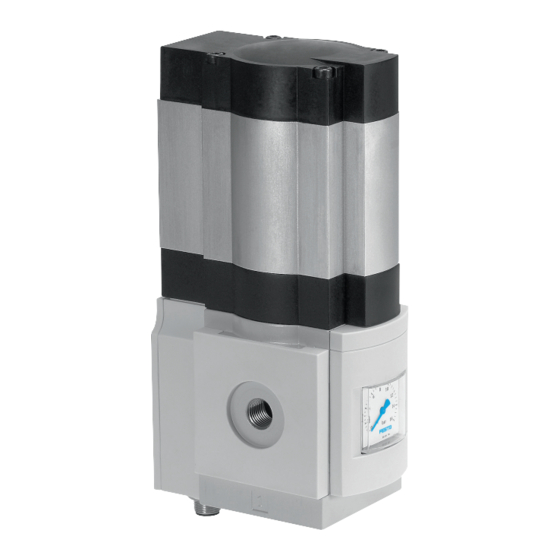
Fig. 1 Product Design
5.2
Function
The product smoothes out pressure fluctuations in pneumatic systems. The elec-
tric drive unit enables the output pressure to be adjusted in the pneumatic
closed-loop controller. The product is controlled via digital input signals. This
determines the direction of rotation of the drive unit and enables the output pres-
sure to be adjusted in an increasing (UP) or decreasing (DOWN) direction. The
pressure control works mechanically.
6
Assembly
1. Observe the flow direction from 1 to 2 è 5.1.1 Product Design.
2. Mount the product using the mounting accessories provided. The opening of
the exhaust valve 2 must not be blocked.
Assembly of module connectors and mounting brackets
è Tab. 1 Documentation on the product.
7
Installation
7.1
Pneumatic Installation
If using fittings with width across flats greater than 24:
•
Push the cover cap upwards and remove it.
If using fittings with width across flats up to 24:
•
Note the screw-in depth of the connector thread.
Product
Screw-in depth
Thread ISO 228
MS6-LRE-1/4
£ 11 mm
MS6-LRE-3/8
£ 12 mm
MS6-LRE-1/2
£ 14 mm
Thread NPT
MS6N-LRE-1/4
£ 10 mm
MS6N-LRE-3/8
£ 10.3 mm
MS6N-LRE-1/2
£ 13.6 mm
Tab. 2 Maximum Screw-in Depth of the Connector Thread
•
Screw the connectors into the pneumatic connections using a suitable sealing
material.
7.2
Electrical Installation
WARNING!
Risk of injury due to electric shock.
•
For the electrical power supply, use only PELV circuits in accordance with IEC
60204-1/EN 60204-1 (Protective Extra-Low Voltage, PELV).
•
Observe the general requirements of IEC 60204-1/EN60204-1 for PELV cir-
cuits.
•
Only use voltage sources that ensure a reliable electric separation from the
mains network in accordance with IEC 60204-1/EN 60204-1.
Protection against electric shock (protection against direct and indirect contact) is
guaranteed in accordance with IEC/DIN EN 602041 by using PELV circuits (elec-
trical equipment of machines, general requirements).
Plug
Pin
Cable colours
Plug M12 supply voltage/input signals
1)
1
Brown
2
White
3
Blue
4
Black
5
Grey
1) Tightening torque: £ 0.5 Nm
Tab. 3 Pin Allocation of Plug M12
1 Pneumatic connection 1:
Input for compressed air
2 Exhaust valve
3 Drive unit
4 Pneumatic connection 2:
Outlet for compressed air
5 Pressure gauge
For MSE6-LRE-...-OP: with operat-
or unit
Function
24 V DC supply voltage
24 V input signal UP
0 V DC
24 V input signal DOWN
FE - functional earth
Advertisement

Related Manuals for Festo MS6-LRE


Summary of Contents for Festo MS6-LRE
- Page 1 Spare parts èwww.festo.com/spareparts. trical equipment of machines, general requirements). Service Plug Cable colours Function Contact your regional Festo contact person if you have technical questions è www.festo.com. Plug M12 supply voltage/input signals Brown 24 V DC supply voltage White 24 V input signal UP Blue 0 V DC...
- Page 2 Plug Cable colours Function Elements dis- Function Description play Plug sensor M8 - only MS6-LRE-...-PI/PU Digits 6 Illuminated Current output pressure is displayed. Brown Not assigned Flashing Current output pressure has exceeded the pressure regulation Blue GND/0 V range. Black Analogue output [kPa] Illuminated Active pressure unit.
- Page 3 Tab. 9 Technical Data, Electrical 2. Separate the applicable connections from the product. Disposal ENVIRONMENT! Send the packaging and product for environmentally sound recycling in accord- ance with the current regulations è www.festo.com/sp. Technical Data 13.1 Technical Data, Mechanical MS6-LRE-… -D5-…...
Need help?
Do you have a question about the MS6-LRE and is the answer not in the manual?
Questions and answers