
Subscribe to Our Youtube Channel
Related Manuals for Definox DPX EBC


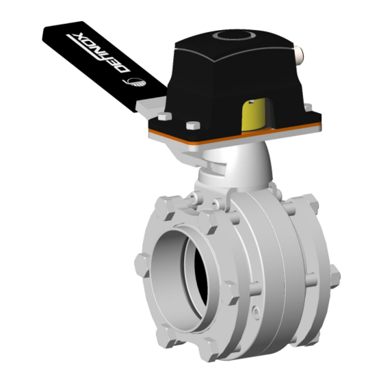
Summary of Contents for Definox DPX EBC
- Page 1 MAINTENANCE MANUAL MANUAL BUTTERFLY VALVE Compact Inter-Flange with IO-LINK MVQ detection www.definox.com NM-283 Index 1 Page 1/15 April 2022...
-
Page 2: Table Of Contents
MAINTENANCE MANUAL TABLE OF CONTENTS 1 CHANGE MANAGEMENT 2 SAFETY 2.1 IMPORTANT INFORMATION: 2.2 GENERAL INFORMATION: 3 INTRODUCTION 4 DISASSEMBLY AND REASSEMBLY OF EBC BUTTERFLY VALVE SUB-ASSEMBLY 5 DISASSEMBLING THE MANUAL SYSTEM 5.1 SEPARATING THE MANUAL SYSTEM: 6 ASSEMBLING THE EBC MANUAL BUTTERFLY VALVE WITH IO-LINK MVQ101 DETECTION 6.1 LIST OF PARTS FOR THE ASSEMBLY 6.2 INSTALLATION OF THE DETECTION ON THE EBC MANUAL VALVE 6.3 IO-LINK MVQ101 DETECTOR SETTING... -
Page 3: Change Management
MAINTENANCE MANUAL 1 CHANGE MANAGEMENT MODIFICATIONS INDEX DATE PAGES New edition April 2022 G. BEGAUD NM-283 Index 1 Page 3/15 April 2022... -
Page 4: Safety
MAINTENANCE MANUAL 2 SAFETY IMPORTANT INFORMATION: Always read the maintenance manual before manipulating the valve Failure to observe these instructions can result in serious bodily injury or loss of life. DANGER! This can result in less serious injuries or damage to the equipment. CAUTION! Electricity can result in serious bodily injury or loss of life. -
Page 5: Introduction
CAUTION! 4 DISASSEMBLY AND REASSEMBLY OF EBC BUTTERFLY VALVE SUB-ASSEMBLY For disassembly, reassembly, and maintenance of DPX EBC sub-assemblies, refer to the maintenance manual: NM-222 for DPX EBC. 5 DISASSEMBLING THE MANUAL SYSTEM SEPARATING THE MANUAL SYSTEM: Remove the handle assembly [1] and [4] from the hub [2a] or [2b] and recover the spring [3]. -
Page 6: Assembling The Ebc Manual Butterfly Valve With Io-Link Mvq101 Detection
6 ASSEMBLING THE EBC MANUAL BUTTERFLY VALVE WITH IO- LINK MVQ101 DETECTION LIST OF PARTS FOR THE ASSEMBLY • IO-LINK MVQ101 Detection Hub / • DPX EBC manual Handle Assembly • Clamping sleeve for connecting • DPX connector for IO-LINK... -
Page 7: Installation Of The Detection On The Ebc Manual Valve
MAINTENANCE MANUAL INSTALLATION OF THE DETECTION ON THE EBC MANUAL VALVE Apply a drop of medium thread locker to the start of the thread of the 4 CHC screws of the hub attachment (valve lubrication instruction sheet NDT-020). Pay attention to the expiry date of the product. - Page 8 MAINTENANCE MANUAL Alignment of the hub/handle assembly: 1 - Take the centring device 7900053. 2 - Position and screw in the centring device (this allows alignment of the hub). 4 - Remove the centring device 3 - Tighten the 4 CHC screws. NM-283 Index 1 Page 8/15...
- Page 9 MAINTENANCE MANUAL Installation of the connecting piece: 1 - Apply a drop of medium thread locker to the start of the flap thread and the linkage part. 2 - Tighten the linkage part with the sleeve 7900052 (tighten and lock the screw to 8 N.m). ...
- Page 10 MAINTENANCE MANUAL Verification: Check the size of the flagpole: 26.65 MAXIMUM MVQ dimension: 26.70 mm (Do not mount the MVQ if the overall dimension is = or greater than 26.70 mm). Take the measurement as close as possible to both sides of the flag. ...
-
Page 11: Io-Link Mvq101 Detector Setting
MAINTENANCE MANUAL IO-LINK MVQ101 DETECTOR SETTING When the valve is opened, the OPEN position appears. When the valve is closed, the indicator remains BLACK. NM-283 Index 1 Page 11/15 April 2022... - Page 12 MAINTENANCE MANUAL LED 5 LED 1 LED 2 PWR LED 3 LED 4 LED 5 Communication status OUT1 LED 1 Steady white valve position open (lit if output 1 is switched) LED 2 PWR Steady green The power is applied to the device LED 3 Not connected Communication status OUT2...
- Page 13 MAINTENANCE MANUAL Setting the Communication threshold 1 (SSC1) open valve: Open the valve. Connect the detector to the mains with the 24VDC power supply, the detector's "PWR" light lights up yellow. Place a metal piece on top of the detector until the LED ring flashes yellow.
-
Page 14: Spare Parts Io-Link Detection Handle Mvq101
MAINTENANCE MANUAL Locking the device Place a metal coin on top of the sensor (approx. 20s) until the LED ring flashes once briefly and then lights up again. The device is locked, parameterisation is no longer possible. Unlocking the device Place a metal coin on top of the sensor (approx. - Page 15 New Berlin – WISCONSIN 53151 – USA Phone: (1) 262 797 5730 - Fax: (1) 262 797 5735 lbuckett@definox-usa.com CHINA DEFINOX Beijing Stainless Steel Equipment Ltd No 18 Anningzhuang East Road – HAIDIAN District BEIJING 100085 – CHINA Phone: (86) 10.6293.4909 - Fax: (86) 10.6293-4835 lk@definox.com.cn...
Need help?
Do you have a question about the DPX EBC and is the answer not in the manual?
Questions and answers