
Related Manuals for Definox Sorio


Summary of Contents for Definox Sorio
- Page 1 MAINTENANCE NOTICE ® Control unit Sorio www.definox.com NM-275 index 09 Page 1/50 September 2021...
-
Page 2: Table Of Contents
On VDCI MC actuator ® 3EV Sorio unit 7.4.1 On VEOX actuator 7.4.2 On VDCI MC actuator ® USE OF THE Sorio UNIT Main Menu Automatic calibration Manual calibration Changing LED colours 8.4.1 Changing RGB LED colour valve open / valve closed: 8.4.2 Color change RGB LED upper valve &... - Page 3 Warnings 8.8.2 Errors ® Sorio SPARE PARTS – unit 1EV ® Sorio Sorio® unit 1EV spare parts list – unit 2EV ® Sorio Sorio® unit 2EV spare parts list – unit 3EV ® Sorio Sorio® unit 3EV spare parts list ®...
-
Page 4: Management Of Evolutions
7009059, 7162260 was 7009310 Update notice April 2021 G. BEGAUD Modification of the base for adaptation of the control top for Sorio VDCI MC PFA without takeoff cylinder DN100 and July 2021 45/46 G. BEGAUD VDCI MC SP / SPC / PMO DN100... -
Page 5: Safety
MAINTENANCE NOTICE SAFETY Important information Always read the maintenance notice before manipulating the valve Failure to observe these instructions can result in serious bodily injury or loss of life. DANGER ! DANGER! This can result in less serious injuries or damage to the equipment. NOTE! Electricity can result in serious bodily injury or loss of life DANGER! -
Page 6: Introduction
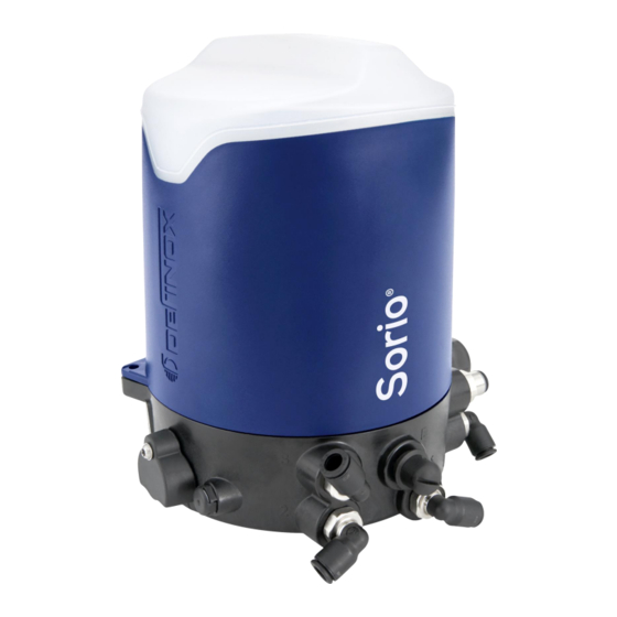
MAINTENANCE NOTICE SORIO Signalling unit INTRODUCTION The new generation Sorio® control unit, intelligent, easy to use and set up, is adaptable to all types of valves. Available in digital, AS-i, IO-Link versions. The SORIO signalling unit can be fitted to Normally Closed (NC), Normally Open (NO), double acting valves. -
Page 7: Assembly
MAINTENANCE NOTICE ASSEMBLY Disassembling the unit 4.1.1 Disassembing the actuator unit The retro information LEDs are diffusing significantly, it is advisable not to look directly into the diffusion beam, otherwise there is a risk of glare. NOTE CAUTION: Before starting any work on the unit, it is important to ensure that the mains supply is switched off, that the air supply is closed and that the circuit is purged. -
Page 8: Disassembling The Components Of The Unit
MAINTENANCE NOTICE 4.1.2 Disassembling the components of the unit Before dismantling the components, identify and disconnect the wires connected to the module, as well as those on the connector. NOTE! Disassembling the module Disassembling the solenoid valve Screw Screw Washer Solenoid... -
Page 9: Reassembling The Signaling Unit
MAINTENANCE NOTICE Reassembling the signaling unit 4.2.1 Reassembling the solenoid valves • Position the solenoid gasket by indexing it on the centring pin of the mounting base. One side of the gasket will come to rest against the orientation piece. •... -
Page 10: Reassembling The Unit On The Actuator
MAINTENANCE NOTICE 4.2.3 Reassembling the unit on the actuator Reassembling the base on the actuator Reassembling the cover • Same as the reverse of the disassembling: Same as the reverse of the disassembling: • • Position the base on the actuator by aligning the Align the fin of the cover with the stopper and indexing pin to the 1/8 Gas hole. -
Page 11: Electrical Connection
MAINTENANCE NOTICE ELECTRICAL CONNECTION Digital / IO Link modules 5.1.1 Digital / IO-Link 1EV module (Ref. 7162001) Terminal With M12 Description Digital number connector Power supply +24V Pin 1 (brown) Power supply GND Pin 3 (blue) PLC in / com Status OK IO-Link Pin 4 (black) -
Page 12: Digital / Io-Link ,2Ev Or 3Ev Module (Ref. 7162002)
MAINTENANCE NOTICE 5.1.2 Digital / IO-Link ,2EV or 3EV module (Ref. 7162002) Pigging Mode Terminal Digital With M12 Description Digital number Pigging Mode connector +24V V+ & V+ Sensor 3 V+ & V+ Sensor 3 Pin 1 (brown) V- & V- Sensor 3 V- &... -
Page 13: As-I Modules
MAINTENANCE NOTICE AS-I modules 5.2.1 AS-i 1EV module (Ref. 7162003) Terminal With M12 Description number 1 solenoid connector (Set-up only) valve AS-i supply + AS-i + +24V Pin 1 (brown) AS-i supply - AS-i - Pin 3 (blue) IO-Link Signal IO-Link Pin 4 (black) Description... -
Page 14: As-I 2Ev Or 3Ev Module (Ref. 7162004)
MAINTENANCE NOTICE 5.2.2 AS-i 2EV or 3EV module (Ref. 7162004) Input table Description De-energized Main energized Upper seat lift energized, Usl Lower seat lift energized, Lsl Description Output table Main, SV-I Usl, SV-II Lsl, SV-III Initiate Auto Setup AS-i Terminal AS-i With M12 Description... -
Page 15: As-I Module Versions
MAINTENANCE NOTICE AS-i MODULE VERSIONS The AS-i LED modules provide the interface between the peripheral devices (solenoid valves, sensors) and the command control system (PLC) via the AS-i network. As standard, AS-i led modules are in version AS-i 3.0, and on request, they are available in version 2.1 and 2.0. -
Page 16: The As-I Network
MAINTENANCE NOTICE The AS-i network The AS-i network can be wired according to a tree configuration, a linear configuration with sections or a star configuration. These three architectures can be used simultaneously. 6.2.1 AS-i power supplies An AS-i power supply is specific to the AS-i network. •... -
Page 17: Technical Specifications Of The As-I Led Modules
MAINTENANCE NOTICE Technical specifications of the AS-i LED modules General specifications 25 … 31.6 VDC AS-i supply voltage 92 mA Current consumed for 1 active solenoid valve and 1 active sensor Electromagnetic compatibility EN61000-6-2, EN61000-6-4 Temperature -10 to +60 °C •... -
Page 18: Pneumatic Connection
MAINTENANCE NOTICE PNEUMATIC CONNECTION ® 1EV Sorio unit 7.1.1 On DP(A)X, DCX3/4 and NEOS actuators MOUNTING VALVE N.C. MOUNTING VALVE N.O. Smooth square Changing from an NC unit To a NO unit • Remove the pneumatic tubes 4/6 28 from the quick couplings 7 and 11 of channels P and 1 of the signalling unit and of the actuator A. -
Page 19: Sorio ® Double Acting Unit
MAINTENANCE NOTICE ® Sorio Double acting unit 7.2.1 On DP(A)X, DCX3/4 and NEOS actuators Smooth square • Connect the quick connector square 11a to the quick connector square 11b with a pneumatic tube 4/6. • Connect the quick connector square 11 to the smooth square with a pneumatic tube 4/6. -
Page 20: 2Ev Sorio ® Unit
MAINTENANCE NOTICE ® 2EV Sorio unit 7.3.1 On VEOX actuator 7.3.2 On VDCI MC actuator Smooth square Smooth square • • Connect the quick connector square 11a to the Connect the quick connector square 11a to the quick connector square 11b with a pneumatic quick connector square 11b with a pneumatic tube ... -
Page 21: 3Ev Sorio ® Unit
MAINTENANCE NOTICE ® 3EV Sorio unit 7.4.1 On VEOX actuator 7.4.2 On VDCI MC actuator Replace the square quick connector 7010116 with a pierced plug 7002496 Smooth square Smooth square • • Connect the quick connector square 11a to the... -
Page 22: Use Of The Sorio Unit
MAINTENANCE NOTICE ® USE OF THE Sorio UNIT Main Menu RGB LED External visualization 5 LEDs in column Status Auto 2 sensitive Manual buttons Tolerance Error Main menu (Level 1) Button Description RGB LED column Depending on current mode Status mode – OK... -
Page 23: Automatic Calibration
MAINTENANCE NOTICE Automatic calibration Note: The automatic calibration is not about VDCI and VDCI MC NOTE! 1) Turn the cover counterclockwise to bring the fin to the stop, then remove the cover by pulling it up. 2) Press the button The Auto LED flashes. -
Page 24: Manual Calibration
MAINTENANCE NOTICE Manual calibration 1) Press the button twice to go to the Manual menu The Manual LED flashes. 2) Press the button for at least 3 seconds to start the manual calibration. 3 sec. The LED column stays fixed on the Manual menu and the upper RGB LED flashes at the colour for valve idle 3) Press the button for at least 3 seconds to save the position for valve idle. - Page 25 MAINTENANCE NOTICE 5) Deactivate the SV1 solenoid valve and wait until the movement of the valve stops. Operations 6, 7, 8 and 9 only for 3EV Units 6) Activate the solenoid valve SV2 and when the upper valve position is reached then press the button for at least 3 seconds to save the upper valve pulse position.
-
Page 26: Changing Led Colours
MAINTENANCE NOTICE Changing LED colours Factory default RGB LED RGB LED Colour Default position Cyan Open position () closed Green Close position (Open position) Flashing green Upper valve pulse Flashing Cyan Lower valve pulse Flashing violet Valve not calibrated Yellow Warning Flashing yellow Calibration in progress... - Page 27 MAINTENANCE NOTICE 3) Confirm the valve idle colour by pressing (The RGB colour chosen for valve idle is displayed for 2 seconds) 4) The valve open colour flashes in RGB LED. (Default Green) Press the button several times until the desired colour for valve open is found x clicks Button Effect...
-
Page 28: Color Change Rgb Led Upper Valve & Lower Valve Pulse (Version 3Ev)
MAINTENANCE NOTICE 8.4.2 Color change RGB LED upper valve & lower valve pulse (version 3EV) 1) Press the button for at least 5 seconds to enter the colour change mode. 5 sec. The RGB LED colour of the lower valve pulse flashes. (Default flashing cyan) 2) Press the button several times until the desired lower valve pulse colour is found x clicks... - Page 29 MAINTENANCE NOTICE 4) The upper valve pulse colour flashes in RGB LED. (Default flashing green) Press the button several times until the desired upper valve pulse colour is found x clicks Button Effect Led column RGB Led Change to Unlit Unlit Choose the colour for...
-
Page 30: Changing Tolerances
MAINTENANCE NOTICE Changing tolerances 1) Go to the Tolerance menu by pressing 3 times the button 2) When the Tolerance LED is flashing, confirm by pressing the button for at least 3 seconds. 3 sec. 3) The current tolerance is displayed on the front LED. Press the button several times to change the tolerance until the desired one is found. - Page 31 MAINTENANCE NOTICE 4) When the Tolerance LED is flashing, confirm by pressing the button for at least 3 seconds. 3 sec. (The selected tolerance stays fixed for 1 second and the LED column returns to the Status menu) NM-275 index 09 Page 31/50 September 2021...
-
Page 32: Pigging Mode
MAINTENANCE NOTICE Pigging mode On units fitted with 3EV modules (Ref. 7162002 or 7162004), it is possible to switch to Pigging mode. This mode allows to connect 2 external detectors for push or block cylinders used on the pigging stations. For the Digital / IO-Link version, it is possible to add a third external detector. - Page 33 MAINTENANCE NOTICE Other functions 8.7.1 Reset options - Factory settings It is possible to revert to the factory settings using the following combination: Simultaneously press the buttons for 15 seconds minimum and less than 30 seconds, the unit will reset and return to the factory settings.
- Page 34 MAINTENANCE NOTICE Diagnostic 8.8.1 Warnings The table below identifies the warning code. Status Auto Manual Tolerance Error Code # Example: Warning Code #13 LED S M T CODE # Feedback / Warning Description Status OK Automatic calibration mode Manual calibration mode Pigging mode Tolerance mode Warning tolerance zone reached...
- Page 35 MAINTENANCE NOTICE 8.8.2 Errors The table below identifies the error code. Status Auto Manual Tolerance Error Code # Example: Error code LED S A M E Code # Error Description Magnetic cam error (Missing or wrong orientation) Solenoid valve error (Missing solenoid valve during automatic calibration) Air network problem External detector error...
- Page 36 MAINTENANCE NOTICE ® Sorio SPARE PARTS – unit 1EV ® Sorio NM-275 index 09 Page 36/50 September 2021...
- Page 37 MAINTENANCE NOTICE Sorio® unit 1EV spare parts list Description Quantity Reference unit plastic cover 7162068 ® Sorio unit stainless steel cover 7162046 ® Sorio 1 depending on 2a 1EV Digital - IO-Link module 7162001 configuration 1EV AS-I 3.0 module 7162003 1 depending on 1EV AS-I 2.1 module...
- Page 38 MAINTENANCE NOTICE – unit 2EV ® Sorio Exit A Exit B Exit A Exit B Cable gland NM-275 index 09 Page 38/50 September 2021...
- Page 39 MAINTENANCE NOTICE Sorio® unit 2EV spare parts list Description Quantity Reference unit plastic cover 7162068 ® Sorio unit stainless steel cover 7162046 ® Sorio 1 depending on 2a 3EV Digital - IO-Link module 7162002 configuration 3EV AS-i 3.0 module 7162004 1 depending on 3EV AS-i 2.1 module...
- Page 40 MAINTENANCE NOTICE – unit 3EV ® Sorio Exit A Exit B Exit A Exit B Cable gland with upper valve pulse detector NM-275 index 09 Page 40/50 September 2021...
- Page 41 MAINTENANCE NOTICE Sorio® unit 3EV spare parts list Description Quantity Reference unit plastic cover 7162068 ® Sorio unit stainless steel cover 7162046 ® Sorio 1 depending on 2a 3EV Digital - IO-Link module 7162002 configuration 3EV AS-i 3.0 module 7162004 1 depending on 3EV AS-i 2.1 module...
- Page 42 MAINTENANCE NOTICE ® Sorio Box - 1EV Double Effect Monostable or Bistable 1EV Double Effect Monostable 1EV Double Effect Bistable NM-275 index 09 Page 42/50 September 2021...
- Page 43 MAINTENANCE NOTICE ® Sorio 1EV Spare parts list Double Effect Monostable or Bistable Description Quantity Reference unit plastic cover 7162068 ® Sorio unit stainless steel cover 7162046 ® Sorio 1 depending on 2a 3EV Digital - IO-Link module 7162002 configuration 3EV AS-i 3.0 module...
- Page 44 MAINTENANCE NOTICE References and dimensions of cams, bases and spacers 9.9.1 Cams Height Threading Tapping Ref. Visual Tools ≥ 2 Nm 7162010 Allen key 2.5 ≥ 2 Nm 7162011 Allen key 2.5 Open-end 7162012 spanner 17 Open-end 7162013 spanner 17 Open-end 7162014 spanner 17...
- Page 45 MAINTENANCE NOTICE 9.9.2 Cams, bases, and spacers references Complete kit: Ref. Ref. Ref. (Cam + screw + Base Spacer Valve Diameter O-ring + base + (§ 9.9.1) (§ 9.9.3) (§ 9.9.4) spacer) DN25 - DN80 7162010 DPAX - Butterfly valves DPAX EBC DN80 actuator DN104 / DN100 - DN150 7162011...
- Page 46 MAINTENANCE NOTICE 9.9.3 Bases Inside Diameter Height Ref. Visual Description diameter Ø D Ø DI 79.5 7162077 Base for actuator center distance 32 79.5 7162190 Base for PEAX actuator 7162141 Base for DCX / VDCI / VEOX actuator 7162212 Base for VDCI VDE / 95 DN125/150 actuator 25.5 79.5 7162211...
- Page 47 Spacer for actuator DCX3/4 BALANCED DN50-80 19.75 15.5 7162319 Spacer for actuator DCX3/4 BALANCED DN100 24.9 15.5 9.9.4.2 VDCI MC PFA Height Counterbore depth Ref. Sorio ® spacer VDCI MC PFA 7162191 Depth 9.5 mm 11.5 7162192 Depth 10 mm DN38/51 7148647 Standard 12.5 10.5...
- Page 48 MAINTENANCE NOTICE 9.9.4.3 VDCI PFA 1991 / 1995 Diameter Height Counterbore depth Ref. Spacer VDCI 95 Ø DN38/51 7140016 Depth 2 mm DN63/76 7140036 Depth 1.5 mm DN80/104 7140158 Depth 1.8 mm DN125/150 7140076 Depth 6 mm NM-275 index 09 Page 48/50 September 2021...
- Page 49 MAINTENANCE NOTICE 9.10 Accessories, cables and vampire clips Reference Description Visual 7162169 Connector cable M12 0.6 m 7162017 Connector cable M12 1 m 7162170 Connector cable M12 2 m 7162165 Connector cable M12 5 m 7008227 Plastic Vampire clip 7008292 Clip-on stainless vampire clip 7008268 Stainless Vampire clip...
- Page 50 New Berlin – WISCONSIN 53151 – USA Tel: (1) 262 797 5730 - Fax: (1) 262 797 5735 lbuckett@definox-usa.com CHINA DEFINOX Beijing Stainless Steel Equipment Ltd No 18 Anningzhuang East Road – HAIDIAN District BEIJING 100085 – CHINA Tel: (86) 10.6293.4909 - Fax: (86) 10.6293-4835 lk@definox.com.cn...
Need help?
Do you have a question about the Sorio and is the answer not in the manual?
Questions and answers