
Related Manuals for Definox DPAX GEN 2


Summary of Contents for Definox DPAX GEN 2
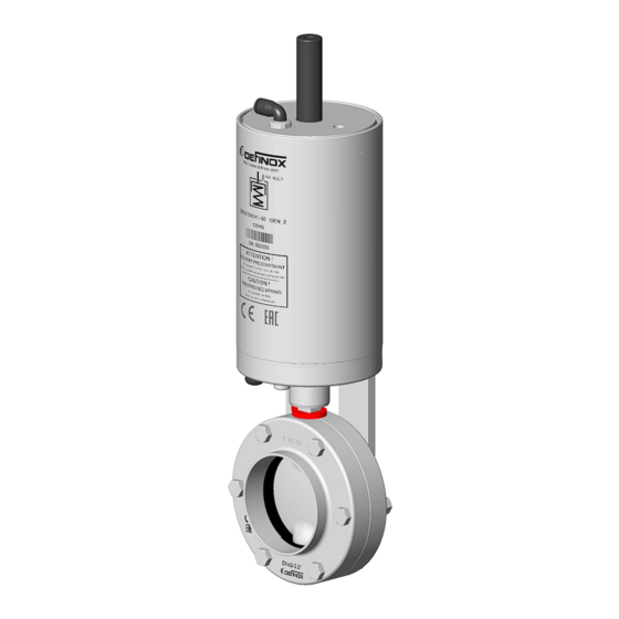
- Page 1 MAINTENANCE MANUAL AUTOMATIC BUTTERFLY VALVE DPAX GEN 2 www.definox.com NM-287 index 1 Page 1/24 May 2023...
-
Page 2: Table Of Contents
MAINTENANCE MANUAL TABLE OF CONTENTS CHANGE MANAGEMENT SAFETY IMPORTANT INFORMATION GENERAL INFORMATIONS INTRODUCTION VALVE DISASSEMBLING DISASSEMBLING THE SIGNALING BLOCK SEPARATION OF THE AUTOMATIC SYSTEM FROM THE VALVE DISASSEMBLING THE BUTTERFLY VALVE DISMANTLING THE MANOEUVRING SYSTEM DISASSEMBLING THE AUTOMATIC ACTUATOR (changing the inner seals) 6.1.1 Disassembling the accessories 6.1.2... -
Page 3: Change Management
MAINTENANCE MANUAL CHANGE MANAGEMENT MODIFICATIONS INDEX DATE PAGES New edition May 2023 G. BEGAUD NM-287 index 1 Page 3/24 May 2023... -
Page 4: Safety
MAINTENANCE MANUAL SAFETY IMPORTANT INFORMATION Always read the maintenance manual before manipulating the valve Failure to observe these instructions can result in serious bodily injury or loss of life. DANGER! This can result in less serious injuries or damage to the equipment. CAUTION! Electricity can result in serious bodily injury or loss of life. -
Page 5: Introduction
MAINTENANCE MANUAL INTRODUCTION CAUTION: Before any intervention, it is necessary to check with the person in charge that the installation is stopped and drained (empty and unpressurised pipes, pumps stopped, tanks isolated or empty). CAUTION! VALVE DISASSEMBLING If the valve is fitted with a signalling box, it may be necessary for disassembly to first separate the signalling assembly from the actuator. -
Page 6: Separation Of The Automatic System From The Valve
MAINTENANCE MANUAL SEPARATION OF THE AUTOMATIC SYSTEM FROM THE VALVE • Unscrew the two screws [55] holding the equipment to the valve half-bodies. • Uncouple the equipment from the valve and remove the position indicator index [52]. • Identify the position of the shutter (valve normally closed or normally open). NM-287 index 1 Page 6/24... -
Page 7: Disassembling The Butterfly Valve
MAINTENANCE MANUAL DISASSEMBLING THE BUTTERFLY VALVE • Unscrew the fixing screws [55] from the nuts [61] on the half-bodies [56], separate them and remove the shutter [60] with its seal [57] and the plug [58] (DN3/4 US and DN25 only). •... -
Page 8: Dismantling The Manoeuvring System
WARNING: This operation must be carried out with suitable tools and with the necessary precautions (SPRING UNDER TENSION) DANGER! Note: After any maintenance work on DEFINOX products, it is imperative to check the proper functioning of the equipment concerned: Sealing, pressure, etc. NOTE 6.1.1 Disassembling the accessories... -
Page 9: 6.1.2 Disassembling The Internal Parts Of The Actuator
MAINTENANCE MANUAL 6.1.2 Disassembling the internal parts of the actuator ATTENTION: SPRING UNDER TENSION WARNING: This operation is dangerous if the tools are not suitable. We recommend that you use a hydraulic press, or a tool as shown in the diagram below. DANGER! Note: Consider a minimum spring travel of L = 100 mm when using the tooling. - Page 10 MAINTENANCE MANUAL With the actuator placed vertically: • Press the base down to release the ring [32]. • Release the ring [32] from its groove with a small screwdriver. • Release the pressure to remove the base [33] with its seals and segment. •...
-
Page 11: Changing The Seals And Reassembling
MAINTENANCE MANUAL CHANGING THE SEALS AND REASSEMBLING INTRODUCTION The components of our valves are listed and marked in these instructions. You can find there the information you need to order spare parts. REASSEMBLING THE AUTOMATIC MANOEUVRING SYSTEM This is the reverse of disassembling. However, please note the following for the automatic system: •... - Page 12 MAINTENANCE MANUAL o Grease the O-ring [46] and fit it into the groove in the barrel [27]. o Turn the barrel [27] over and fit the guide [47]. Note: The bearing flanges [39] have 1 rough side Face with radius and 1 radiused side.
- Page 13 MAINTENANCE MANUAL o Insert the plastic retaining washer [38] (paying (attention to the direction, shoulder side up to centre the spring) into the barrel [27] then remove the guide [47]. o Lubricate the inside of the bronze rollers [36] and place them on the pins in the barrel [27].
- Page 14 MAINTENANCE MANUAL o Grease the seal [45] and fit it in place, grease the pitch of the drive cam [34]. pitch o Position the shaft [37] in the square of the drive cam [34]. o Install the guide [49] by screwing it onto the drive cam assembly.
- Page 15 MAINTENANCE MANUAL o Place the cylinder base [33] on the drive cam [34] using the guide [48] to avoid damaging the U-joint. Remove the guide after fitting the cylinder base. o Push the base about 1 cm under the ring groove, fit the ring [32] and check that it is well positioned in its groove before reassembling the press.
- Page 16 MAINTENANCE MANUAL CHANGING THE ACTUATOR'S CONFIGURATION GEN 2 Conversion of a GEN 2 single-acting actuator to double-acting: After dismantling the air connector [28], the pierced plug [29], the CHC screw [30] and the lock washer [31]. Place the actuator vertically on the press: •...
-
Page 17: Reassembling The Butterfly Valve
MAINTENANCE MANUAL REASSEMBLING THE BUTTERFLY VALVE This operation is carried out in the reverse order to dismantling, but the following advice should be followed: • Apply a suitable grease (such as Paraliq 703, see section 8.8) to the guides of the shutter, the ½... -
Page 18: Spare Parts
MAINTENANCE MANUAL SPARE PARTS BUTTERFLY VALVE SEALS Type 1 Type 2 Type 3 Type 3 can be identified by a "DPX3" marking on the seal. EPDM SILICONE FKM Food Year HNBR SMS DIN Food Acid-proof ¾’’ 7009370 7009400 ... -
Page 19: Manual Butterfly Valve
MAINTENANCE MANUAL MANUAL BUTTERFLY VALVE DPX3 identifiable by the marking on the half- body "DPX3" and shutter "3". Rep: 55 Rep: 56 Rep: 57 Rep: 58 Rep: 59 Rep: 60 Rep: 61 Year ½ Body TH Screw Nb Seal Ring Shutter Nut Hu 316L... -
Page 20: Single-Acting Automatic Actuator Dn3/4 Us - 80 And 100 - 104
MAINTENANCE MANUAL SINGLE-ACTING AUTOMATIC ACTUATOR DN3/4 US - 80 and 100 - 104 Seal kit family: NM-287 index 1 Page 20/24 May 2023... -
Page 21: Double-Acting Automatic Actuator Dn3/4 Us - 80 And 100 - 104
MAINTENANCE MANUAL DOUBLE-ACTING AUTOMATIC ACTUATOR DN3/4 US - 80 and 100 - 104 Seal kit family: NM-287 index 1 Page 21/24 May 2023... -
Page 22: List Of Spare Parts For Manual And Automatic Actuators
MAINTENANCE MANUAL LIST OF SPARE PARTS FOR MANUAL AND AUTOMATIC ACTUATORS Description DN3/4 US - 80 DN100 - 104 7030646 7030799 Actuator barrel Adjustable male elbow 7010116 Pierced plastic plug 7002496 7006984 CHC Screw 7002606 7030821 Lock washer 7380174 Ring 7030619 Cylinder base 7030620... -
Page 23: List Of Actuator Seal Kit Part Numbers
MAINTENANCE MANUAL LIST OF ACTUATOR SEAL KIT PART NUMBERS ACTUATOR SEALS KIT DESCRIPTION DN3/4 US - 104 - DPAX DN3/4 US - 104 7072477 DETAILS OF SEAL KITS 8.7.1 NBR actuator seal kits: DN3/4 US - 104 Diameter Kit N° 7072477 Rep. - Page 24 New Berlin – WISCONSIN 53151 – USA Phone: (1) 262 797 5730 - Fax: (1) 262 797 5735 CHINA DEFINOX Beijing Stainless Steel Equipment Ltd No 18 Anningzhuang East Road – HAIDIAN District BEIJING 100085 – CHINA Phone: (86) 10.6293.4909 - Fax: (86) 10.6293-4835 The technical characteristics of the products in this document are given as an indication and can be modified according to technological developments.
Need help?
Do you have a question about the DPAX GEN 2 and is the answer not in the manual?
Questions and answers