Table of Contents
Advertisement
Quick Links
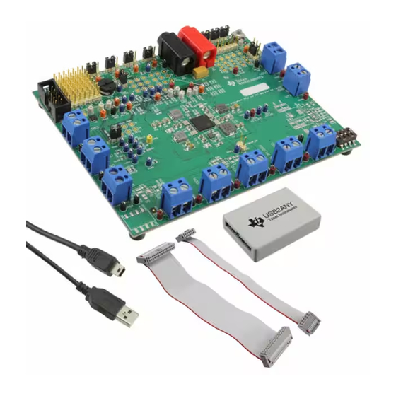
The TPS650830EVM-095 evaluation module is a fully assembled and tested circuit for evaluating the
TPS650830 6-channel power management integrated circuit. The TPS650830EVM provides a platform for
a user or designer to evaluate the TPS650830. It has the capabilities to experiment with the part in a
holistic design approach for computing power and in a generic mode such as if the TPS650830 is placed
into a new experimental application. This document includes instructions and results of typical electrical
performance characteristics, connector and test point descriptions, setup instructions, schematics, printed-
circuit-board (PCB) layouts and the bill of materials (BOM). Throughout this user's guide, the abbreviations
EVM, TPS650830EVM, and the term evaluation module are synonymous with the TPS650830EVM-095,
unless otherwise noted.
...................................................................................................................
1
1.1
1.2
1.3
2
3
3.1
3.2
3.3
4
4.1
4.2
4.3
.........................................................................................................................
5
5.1
5.2
5.3
6
7
1
2
3
4
5
6
7
8
9
10
11
12
13
..............................................................................................................
..........................................................................................................
.......................................................................................................
..............................................................................................
.........................................................................................
................................................................................................
...............................................................................................
............................................................................................................
.............................................................................................................
...................................................................................................
....................................................................................................
.............................................................................................
.............................................................................................................
..............................................................................
..............................................................................
.................................................................................
....................................................................................
.................................................................................
..............................................................................................
....................................................................................
.........................................................................................................
Copyright © 2014, Texas Instruments Incorporated
TPS650830EVM-095
Contents
................................................................
...............................................................
....................................................................
.....................................................................
List of Figures
.............................................................................
.......................................................................
........................................................
.....................................................
.....................................................................
User's Guide
SLVUAD6 - December 2014
2
2
2
2
3
5
5
7
9
10
10
10
10
11
11
11
12
14
18
5
5
6
6
7
8
9
11
12
12
14
15
15
1
Advertisement
Table of Contents

Related Manuals for Texas Instruments TPS650830EVM-095


Summary of Contents for Texas Instruments TPS650830EVM-095
-
Page 1: Table Of Contents
SLVUAD6 – December 2014 TPS650830EVM-095 The TPS650830EVM-095 evaluation module is a fully assembled and tested circuit for evaluating the TPS650830 6-channel power management integrated circuit. The TPS650830EVM provides a platform for a user or designer to evaluate the TPS650830. It has the capabilities to experiment with the part in a holistic design approach for computing power and in a generic mode such as if the TPS650830 is placed into a new experimental application. -
Page 2: Introduction
EVM to its max power outputs. • Tablets • Human Machine Interface • Infotainment Systems • FPGA System Power Microsoft, Windows are registered trademarks of Microsoft Corporation. TPS650830EVM-095 SLVUAD6 – December 2014 Submit Documentation Feedback Copyright © 2014, Texas Instruments Incorporated... -
Page 3: Tps65083Xevm Electrical Performance Specifications
= 10.5 kΩ, L = 1 µH Current Limit Low-Side MOSFET Low Side Rds = 7mΩ, R = 10.5 9.38 LIMF kΩ Switching frequency NVDCZ = HIGH SLVUAD6 – December 2014 TPS650830EVM-095 Submit Documentation Feedback Copyright © 2014, Texas Instruments Incorporated... - Page 4 VLDO1, VTT DDRID shorted to GND, VR4/VDDQ 0.6V supplies VINLDO1 = 1.2V Output current of LDO1 Source Current Limit of LDO1 Sink Current Limit of LDO1 TPS650830EVM-095 SLVUAD6 – December 2014 Submit Documentation Feedback Copyright © 2014, Texas Instruments Incorporated...
-
Page 5: Tps650830Evm Schematics
TPS650830EVM Schematics www.ti.com TPS650830EVM Schematics TPS650830 Voltage Rails Figure 1. TPS650830EVM VR1 and VR2 Schematic Figure 2. TPS650830EVM VR3 and VR4 Schematic SLVUAD6 – December 2014 TPS650830EVM-095 Submit Documentation Feedback Copyright © 2014, Texas Instruments Incorporated... -
Page 6: Tps650830Evm Vr5 And Ldo1 Schematic
TPS650830EVM Schematics www.ti.com Figure 3. TPS650830EVM VR5 and LDO1 Schematic Figure 4. TPS650830EVM VR Outputs Schematic TPS650830EVM-095 SLVUAD6 – December 2014 Submit Documentation Feedback Copyright © 2014, Texas Instruments Incorporated... -
Page 7: Tps650830 Controls And Tps650830 Features
TPS650830EVM Schematics www.ti.com TPS650830 Controls and TPS650830 Features Figure 5. TPS650830EVM Controls Schematic SLVUAD6 – December 2014 TPS650830EVM-095 Submit Documentation Feedback Copyright © 2014, Texas Instruments Incorporated... -
Page 8: Tps650830Evm Tps650830 Schematic
TPS650830EVM Schematics www.ti.com Figure 6. TPS650830EVM TPS650830 Schematic TPS650830EVM-095 SLVUAD6 – December 2014 Submit Documentation Feedback Copyright © 2014, Texas Instruments Incorporated... -
Page 9: Discretes And Pols
TPS650830EVM Schematics www.ti.com Discretes and POLs Figure 7. TPS650830EVM Discretes and POLs Schematic SLVUAD6 – December 2014 TPS650830EVM-095 Submit Documentation Feedback Copyright © 2014, Texas Instruments Incorporated... -
Page 10: Connectors, Switches And Test Point Descriptions
VR2 and VR3 are already on before any enable switch asserting high. They are enabled by DPWROK and LDO3, respectively, with LDO3 enabled when VIN > UVLO. TPS650830EVM-095 SLVUAD6 – December 2014 Submit Documentation Feedback Copyright © 2014, Texas Instruments Incorporated... -
Page 11: Setup
To install the GUI, first download the GUI from the Tools & Software folder at http://www.ti.com/product/TPS650830/toolssoftware. Once the zip file is open, simply double-click the Setup TPS65083xEVM.msi file. Follow the recommended prompts for installation. SLVUAD6 – December 2014 TPS650830EVM-095 Submit Documentation Feedback Copyright © 2014, Texas Instruments Incorporated... -
Page 12: Running The Software
Click on the TPS65083xEVM icon to start the software. If no icon appears on the host computer, then use the start button in the lower left corner of the screen to browse the program folders to find the software. The default directory for software installation is Program Files\Texas Instruments\TPS65083xEVM. Figure 10 is a diagram of the GUI and beneath the figure are descriptions of each feature that the GUI has to offer. - Page 13 (F) = Auto Read – User can select to read all registers or just a single register every 1, 5, 10, or 20 seconds, as desired. SLVUAD6 – December 2014 TPS650830EVM-095 Submit Documentation Feedback Copyright © 2014, Texas Instruments Incorporated...
-
Page 14: Tps65083Xevm Assembly Drawings And Layout
TPS65083xEVM Assembly Drawings and Layout Figure 11 through Figure 18 show the design of the TPS65083xEVM printed-circuit board. Figure 11. TPS65083xEVM Component Placement (Viewed From Top) TPS650830EVM-095 SLVUAD6 – December 2014 Submit Documentation Feedback Copyright © 2014, Texas Instruments Incorporated... -
Page 15: Tps65083Xevm Bottom Component Placement (X-Ray View)
TPS65083xEVM Assembly Drawings and Layout www.ti.com Figure 12. TPS65083xEVM Bottom Component Placement (X-Ray View) SLVUAD6 – December 2014 TPS650830EVM-095 Submit Documentation Feedback Copyright © 2014, Texas Instruments Incorporated... -
Page 16: Tps65083Xevm Top Copper (Viewed From Top)
Figure 14. TPS65083xEVM GND Layer (Viewed From Top) (X-Ray View From Top) Figure 15. TPS65083xEVM Signal 1 Figure 16. TPS65083xEVM Multi 1 (X-Ray View From Top) (X-Ray View From Top) TPS650830EVM-095 SLVUAD6 – December 2014 Submit Documentation Feedback Copyright © 2014, Texas Instruments Incorporated... - Page 17 Figure 18. TPS65083xVM Signal 2 (X-Ray View From Top) (X-Ray View From Top) Figure 19. TPS65083xEVM Power Layer Figure 20. TPS65083xEVM Bottom Copper (X-Ray View From Top) (X-Ray View) SLVUAD6 – December 2014 TPS650830EVM-095 Submit Documentation Feedback Copyright © 2014, Texas Instruments Incorporated...
-
Page 18: Bill Of Materials
Inductor, Drum Core, Powdered Iron, 3.3 µH, 4.5 A, 0.052 ohm, SMD Inductor, 5.2x1.6x5.2mm PIMB051H-3R3MS Cyntec LBL1 Thermal Transfer Printable Labels, 0.650" W x 0.200" H - 10,000 per PCB Label 0.650"H x THT-14-423-10 Brady roll 0.200"W TPS650830EVM-095 SLVUAD6 – December 2014 Submit Documentation Feedback Copyright © 2014, Texas Instruments Incorporated... - Page 19 CTS Electrocomponents 11.93x6.95mm, Pitch 2.54mm SH-J1, SH-J2, SH-J3, SH-J4, SH-J5, Shunt, 100mil, Gold plated, Black Shunt 2 pos. 100 mil 881545-2 TE Connectivity SH-J6, SH-J7, SH-J8, SH-J9 SLVUAD6 – December 2014 TPS650830EVM-095 Submit Documentation Feedback Copyright © 2014, Texas Instruments Incorporated...
-
Page 20: Submit Documentation Feedback
Simple and Flexible High Input Voltage PMU for Mobile Computers, ZCG0159A TPS650830ZCGR Texas Instruments ZCG0159A Quad Channel Load Switch with GPIO and I2C Control, RLW0020A RLW0020A TPS22993PRLW Texas Instruments TPS650830EVM-095 SLVUAD6 – December 2014 Submit Documentation Feedback Copyright © 2014, Texas Instruments Incorporated... - Page 21 STANDARD TERMS AND CONDITIONS FOR EVALUATION MODULES Delivery: TI delivers TI evaluation boards, kits, or modules, including any accompanying demonstration software, components, or documentation (collectively, an “EVM” or “EVMs”) to the User (“User”) in accordance with the terms and conditions set forth herein. Acceptance of the EVM is expressly subject to the following terms and conditions.
- Page 22 FCC Interference Statement for Class B EVM devices NOTE: This equipment has been tested and found to comply with the limits for a Class B digital device, pursuant to part 15 of the FCC Rules. These limits are designed to provide reasonable protection against harmful interference in a residential installation.
- Page 23 【無線電波を送信する製品の開発キットをお使いになる際の注意事項】 本開発キットは技術基準適合証明を受けておりません。 本製品のご使用に際しては、電波法遵守のため、以下のいずれかの措置を取っていただく必要がありますのでご注意ください。 1. 電波法施行規則第6条第1項第1号に基づく平成18年3月28日総務省告示第173号で定められた電波暗室等の試験設備でご使用 いただく。 2. 実験局の免許を取得後ご使用いただく。 3. 技術基準適合証明を取得後ご使用いただく。 なお、本製品は、上記の「ご使用にあたっての注意」を譲渡先、移転先に通知しない限り、譲渡、移転できないものとします。 上記を遵守頂けない場合は、電波法の罰則が適用される可能性があることをご留意ください。 日本テキサス・インスツルメンツ株式会社 東京都新宿区西新宿6丁目24番1号 西新宿三井ビル 3.3.3 Notice for EVMs for Power Line Communication: Please see http://www.tij.co.jp/lsds/ti_ja/general/eStore/notice_02.page 電力線搬送波通信についての開発キットをお使いになる際の注意事項については、次のところをご覧くださ い。http://www.tij.co.jp/lsds/ti_ja/general/eStore/notice_02.page SPACER EVM Use Restrictions and Warnings: 4.1 EVMS ARE NOT FOR USE IN FUNCTIONAL SAFETY AND/OR SAFETY CRITICAL EVALUATIONS, INCLUDING BUT NOT LIMITED TO EVALUATIONS OF LIFE SUPPORT APPLICATIONS.
- Page 24 Notwithstanding the foregoing, any judgment may be enforced in any United States or foreign court, and TI may seek injunctive relief in any United States or foreign court. Mailing Address: Texas Instruments, Post Office Box 655303, Dallas, Texas 75265 Copyright © 2014, Texas Instruments Incorporated...
- Page 25 IMPORTANT NOTICE Texas Instruments Incorporated and its subsidiaries (TI) reserve the right to make corrections, enhancements, improvements and other changes to its semiconductor products and services per JESD46, latest issue, and to discontinue any product or service per JESD48, latest issue.
- Page 26 Mouser Electronics Authorized Distributor Click to View Pricing, Inventory, Delivery & Lifecycle Information: Texas Instruments TPS650830EVM-095...
Need help?
Do you have a question about the TPS650830EVM-095 and is the answer not in the manual?
Questions and answers