Table of Contents
Advertisement
Quick Links
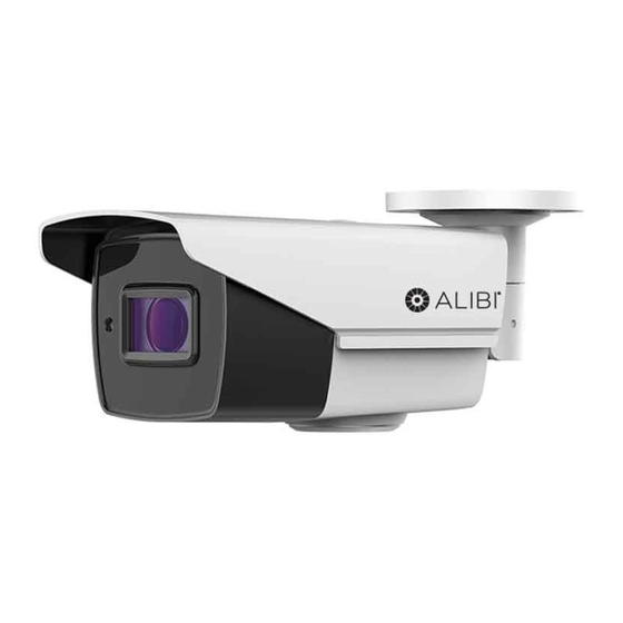
ALI-TS4015R 5MP HD-TVI 135 ft IR
Varifocal Outdoor Bullet Camera
Quick Installation Guide
The ALIBI ALI-TS4015R indoor/outdoor HD-TVI bullet cameras include a high sensitivity sensor with the
ability to send HD video across standard coaxial cable. This camera features:
5 MP Megapixel High Performance CMOS
•
135 ft Smart Full Frame IR
•
Motorized 2.8 ~ 12 mm VF lens
•
OSD menu (up-the-coax OSD control), Digital Noise Reduction (DNR), Smart IR, True Day/Night
•
IP67 Weather rated housing
•
Compatible with a 5 MP HD-TVI recorder (HD-TVI DVR)
•
Can be installed with optional ALI-AJ1 junction box
•
Adjustable sun shield
Lens
Photosensor
Maintenance access cover
ALI-TS4015R camera
Camera drop cable connectors
What's in the box
Camera assembly
•
Mounting hardware
•
Video test adapter cable
•
Drill template
•
This instruction guide
•
What you need
To install the camera, you will need:
12 Vdc or 24 Vac power source. See Specifications for requirements
•
Tools and additional fasteners (may be required) for mounting the camera
•
Phillips #2 screwdriver
•
Video and power extension cable
•
HD-TVI or CVBS video setup monitor (optional)
•
www.observint.com
1
Mounting base
Adjustable
mounting
bracket
Camera body
HD-TVI video BNC connector
Terminal polarity
Power Connector
Installation
Before installation:
Make sure that the device is in good condition and all the assembly parts are included.
•
Check the specification of the products for the installation environment.
•
Make sure that the wall or the ceiling is strong enough to withstand 3 times the weight of the camera.
•
To avoid fire or shock hazard, use only UL listed power supplies. Verify that the power supply will
•
provide the rated voltage and wattage for the camera. See the Specifications section.
During installation:
Camera Lens: Handle the camera carefully to prevent scratching or soiling the lens. If the lens or IR
•
array shield becomes soiled, clean it only with approved products. See the
Power supply: Camera drop cable: The camera drop cable includes two connectors:
•
Video BNC connector: For transmission of the video signal across a coax (75 Ω) extension
—
cable to an HD-TVI compatible recorder.
Power connector: When applying power, observe the power polarity. See the picture to the
—
left for the connector polarity configuration.
Mounting the camera
An ALI-TS4015R camera can be mounted directly to a wall or ceiling, or with a junction box. The surface
should support at least three times the weight of the camera and junction box (if used). The video/power
drop cable from the camera can be routed either through mounting surface or through a cable channel in
the mounting base.
Mounting the camera directly to a wall or ceiling
•
Typical ceiling mounting
If mounting the camera on a wall, ensure that the mounting bracket "UP" label is positioned at
the top.
NOTE
If mounting the camera on a ceiling, orient the mounting base so that the cable channel is pointing
away from any source of water, dust, and other contaminates.
1.
Using the drill template provided, mark the location of the screws that anchor the mounting base
to the mounting surface. See the note above. If you are routing the drop cable through mounting
surface, also mark the position of the hole for the drop cable.
2.
Drill holes for the screws that anchor the base to the mounting surface. The mounting hardware
provided is appropriate for most surfaces. However, depending on the surface materials, more
appropriate fasteners may be required.
3.
If routing the drop cable through the mounting surface, drill a 5/8" hole in the middle of the drill
template.
4.
Route the drop cable through the hole in the mounting surface, or through the cable channel in the
mounting base, then attach the camera assembly to the surface using the appropriate fasteners.
5.
Connect the camera drop cable to video and power extension cables as required. If using 12 Vdc
power, observe the polarity embossed on the power connector. See the photo above.
6.
Connect the other end of the video extension cable to an HD-TVI DVR.
Drop cable connectors are not waterproof. Seal if needed.
NOTE
7.
Connect the other end of the power extension cable to a 12 Vdc (observe polarity - see page 1) or
24 Vac power source.
section.
ALI-TS4015R_CQ
180403
Advertisement
Table of Contents

Subscribe to Our Youtube Channel
Related Manuals for ALIBI ALI-TS4015R


Summary of Contents for ALIBI ALI-TS4015R
- Page 1 Mounting the camera An ALI-TS4015R camera can be mounted directly to a wall or ceiling, or with a junction box. The surface should support at least three times the weight of the camera and junction box (if used). The video/power...
- Page 2 You can open the OSD menu system using the built-in joystick on the camera, from either the HD-TVI DVR Live View display or through remote login to the ALIBI recorder. “UP”...
- Page 3 OSD menu navigation For the ALIBI Recorder: Navigation and settings in the OSD are made through direction keys and the Iris + and Iris - buttons in the HD-TVI DVR PTZ Control panel. See below.
- Page 4 BRIGHTNESS: Brightness refers to the brightness of the image. You can set the brightness value from • 1 to 10 to darken or brighten the image. The higher the brightness value, the brighter the image. EXPOSURE MODE: You can set EXPOSURE mode as GLOBAL or BLC. •...
- Page 5 VIDEO SETTING Menu Power Consumption 9.5 W max Move the cursor to VIDEO SETTING and press the confirm button to enter the submenu. In this menu you Protection Level IP67 can adjust CONTRAST, SHARPNESS, COLOR GAIN, DNR and MIRROR settings. Material Metal IR Range...
Need help?
Do you have a question about the ALI-TS4015R and is the answer not in the manual?
Questions and answers