Table of Contents
Advertisement
Quick Links
Thank you very much for choosing the Yoshitake's product. To ensure the correct and safe use of
the product, please read this manual before use. This manual shall be kept with care for future
references. The symbols used in this manual have the following meanings.
Warning
Caution
1. Specifications···························································· 1
2. Nominal size selection ················································ 2
3. Appearance and dimensions ····································· 3-4
4. Structure ·································································· 5
5. Operation ································································· 5
6. Operating example ·················································· 6-7
7. Storage ··································································· 8
8.1 Installation for body part ······································· 8-9
8.2 Wiring and piping ············································· 10-12
8.3 Test run ····························································· 13
8.4 Positioner readjustment ···································· 13-16
9. Warning and caution for use ······································· 16
10.1 Troubleshooting ················································· 17
10.2 Warning and caution for maintenance ····················· 18
10.3 Dairy inspection ················································· 18
10.4 Regular inspection ············································· 18
10.5 Replacing gaskets, packings and positioners ············ 18
MODEL CT-1
CONTROL VALVE
PRODUCT MANUAL
This symbol indicates a potentially hazardous situation that, if not
avoided, could result in death or serious injury.
This symbol indicates a hazardous situation that, if not avoided, may
result in minor or moderate injury or may result in only property
damage.
Table of Contents
.
■ EPDT-318a ■
Advertisement
Table of Contents

Related Manuals for Yoshitake CT-1


Summary of Contents for Yoshitake CT-1
-
Page 1: Table Of Contents
CONTROL VALVE PRODUCT MANUAL Thank you very much for choosing the Yoshitake’s product. To ensure the correct and safe use of the product, please read this manual before use. This manual shall be kept with care for future references. The symbols used in this manual have the following meanings. -
Page 2: Specifications
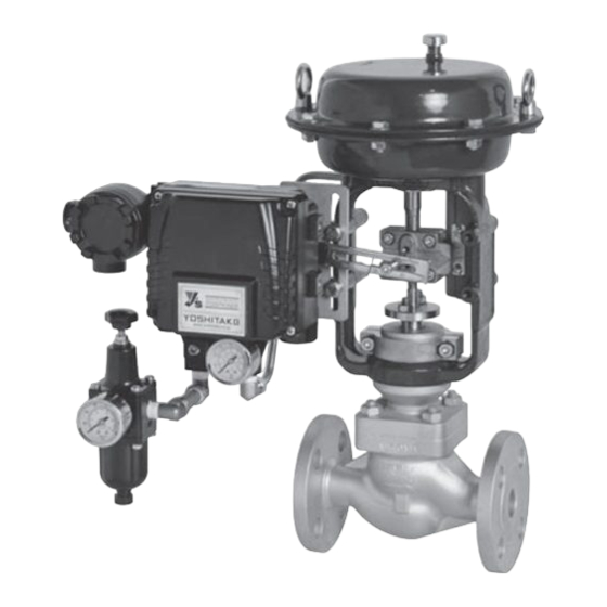
This is the diaphragm type control valve that controls the pressure, flow rate, liquid surface and temperature by using electrical/pneumatic positioner 1. Specifications Model CT-1 Size 15~100A Steam, Air, Cold and hot water, Oil, Control... -
Page 3: Nominal Size Selection
2. Nominal size selection The appropriate nominal size can be calculated by obtaining the Cv value for the operating conditions in question, as shown below. 【In case of steam application】 > ≦ Δ :Inlet press.(MPa・A) W:Max. steam flow rate(kg/h) :Reduced press.(MPa・A) -P... -
Page 4: Appearance And Dimensions
3. Appearance and dimensions (mm) Size Stroke Weight(kg) 100A *In case of including accessories, it is provided as following condition. [EP-1type electrical/pneumatic positioner] Type EP-1 4-20mA Electrical/pneumatic positioner Current signal input G 1/2 Compressed air input Air regulator ■ EPDT-318a ■... - Page 5 (mm) Size 100A [EP-1S type smart positioner] Current signal Input G1/2 Compressed air input Type EP-1S 4-20mA Smart positioner Air regulator (mm) Size 100A ■ EPDT-318a ■...
-
Page 6: Structure
4. Structure Drive parts (Actuator) Upper diaphragm case Spring Eye bolt Diaphragm bolt Diaphragm follower Diaphragm Air inlet Bottom diaphragm case Diaphragm rod Name plate Connector ⑭ Indicator plate ⑱ Yoke ⑬ Nut ⑳ Gland packing ⑥ Nut ⑪ Gland flange ⑮ Cage ④... -
Page 7: Operating Example
【Example of pressure control】 Valve action Signal Fluid (Open degree of Controller valve ) Full Pressure 20mA opened Press.:Min. DC4-20mA gauge (100%) CT-1 Control valve Signal Open Press.: (EP-1) Pressure increase transmitter Decrease Full closed Press.: (0%) Max. [Example of flow control】 DC4-20mA... - Page 8 Valve action Signal (Open degree of Tank valve) Pressure gauge 20mA Full opened Water level: (100%) Surge Level sensor CT-1 Control valve (EP-1) Controller Signal Water level: increase Open Increase Tank DC4-20mA Input signal Water level: Full closed No change (0%) 【Example of temperature control】...
-
Page 9: Storage
7. Storage Please storage the product in the package by installation. During storage, please follow these points. * After open the package for checking product, please storage into original package again. * Do not storage the product where rain falls, temperature is above 60℃, and dust or mist make damage for the product. - Page 10 Caution (1) Do not disassemble the valve unreasonably *Disassembling the valve at your discretion may affect the original performance (2) Remove foreign matter and scales from the lines before connecting the valve. (3) Install the stop valve before and after the control valve (4) To ensure the connect properly without any leakage.
-
Page 11: Wiring And Piping
8.2 Wiring and piping Warning (1) Electrical wiring must be done by expert or professional person. This product is not available for the place (Atmosphere) where have the retention of explosive gas. *Since it is not in the explosion-proof structure, there is a danger of fire. (3) When having the wiring work, please do the work in an environment where does not enter the rainwater or surrounding water. - Page 12 Fig. 7 【How to connect the signal cable to the pneumatic positioner】(In case of EP-1 type) ・When purchasing the goods with accessories, it is delivered by the structure with shown in Fig. 6. Please draw the signal cable from the external DC signal connection port shown in Fig.6.
- Page 13 【How to connect the signal cable to smart positioner】(In case of EP-1S type) ・When purchasing the goods with accessories, it is delivered by the structure with shown in Fig. 7. Please draw the signal cable from the external DC signal connection port shown in Fig.7.
-
Page 14: Test Run
8.3 Test run If the product comes with accessories, it is shipped with positioner set to zero point and the span adjusted, but it may be dropped or received impact during transportation or installation, so before operation, be sure to have a test run. Caution The product operates while a test run. - Page 15 (2) Supply air pressure by the air regulator, and input the signal (4mA DC) of zero opening into the positioner. Then turn the knob of the zero- adjustment part clockwise or counterclockwise to align the initial point (zero point) of the actuator.
- Page 16 【For EP-1S smart positioner】 EP-1S type has auto-calibration function, so auto-calibration can be done the positioner readjustment. * Method of auto-calibration (See Fig.11-13) ①Confirm display works (power is supplied) and air is supplied to positioner. ②Loosen screw on the cover of positioner (4point) and remove the cover. Cover Example of display (Power is supplied)
-
Page 17: Warning And Caution For Use
Push Push Enter key Enter key Push 6sec. Enter key Calibration starts Push Enter key Calibration is completed Fig. 13 ④Auto-calibration is completed when display shows standard indication as Fig.13. Mount cover on the positioner and fix by tightening screw. Please put cover as display can be shown. -
Page 18: Maintenance And Inspection
10.Maintenance and inspection 10.1 Troubleshooting (Please see the structure described 4) Problem Cause Solution 1.Operating pneumatic 1.Please confirm the presence or pressure or external signal absence of the operating air are not supplied. (more than 0.35MPa) by the pressure gauge, etc. And confirm the external signal tester by using tester. -
Page 19: Warning And Caution For Maintenance
10.5 Replacing gaskets, packings and positioners For disassembling the product by replacing the gasket, packing, or positioner, please refer to SM-741 "CT-1 Disassembly and Assembly Procedure". Although it varies greatly depending on the use conditions, the recommended period for replacing gaskets and packings is about two years. -
Page 20: Warranty Information
Fire, flood, earthquake, thunder and other natural disasters. Consumable parts such as O-ring, gasket, diaphragm and etc. Yoshitake is not liable for any damage or loss caused by malfunction or defect of the product. INTERNATIONAL DEPT. 955-5, Miyamae, Irukadeshinden, Komaki, Aichi, 485-0084, Japan...
Need help?
Do you have a question about the CT-1 and is the answer not in the manual?
Questions and answers