Table of Contents
Advertisement
Quick Links
Thank you very much for purchasing our solenoid valves.
Please read this instruction manual thoroughly before using the solenoid valves, so
that you may do so correctly and safely. Please carefully store this bulletin in a
handy place.
-----The following safety symbols are used in this manual.-----
This symbol indicates a potentially hazardous situation that, if not
Warning
avoided, could result in death or serious injury.
This symbol indicates a hazardous situation that, if not avoided, may
Caution
result in minor or moderate injury. ("Caution" may also be used to
indicate other unsafe practices or risks of property damage.)
1.Overview········································································································ 1
2.Specifications & Performance ····························································· 1
3.Dimensions & Weight ········································································ 2~3
4.Operation ······································································································ 4
5.1 Nominal Size Selection Chart ·············································· 5~9
5.2 Calculating the Nominal Size ···················································· 10
6.Installation
6.1 Piping Example ················································································ 10
6.2 Wiring Method ·················································································· 11
6.3 Warning & Caution for Installation ·········································· 12
7.1 Warning & Caution for Operation ············································ 13
7.2 Test Working ···················································································· 13
8.1 Warning & Caution for Maintenance ······································ 14
8.2 Troubleshooting ·············································································· 15
8.3 Disassembly Procedure ······························································· 15
8.4 Disassembly Drawing ························································ 16~17
After Sales Service
DP-10 Series
TYPE DP-10・13, TYPE DP-10D・13D
TYPE DP-12・14, TYPE DP-12D・14D
TYPE DP-15・17, TYPE DP-15D・17D
TYPE DP-16・18, TYPE DP-16D・18D
Instruction Manual
Contents
■EPDT-028d■
Advertisement
Table of Contents

Related Manuals for Yoshitake DP-10 Series


Summary of Contents for Yoshitake DP-10 Series
-
Page 1: Table Of Contents
DP-10 Series TYPE DP-10・13, TYPE DP-10D・13D TYPE DP-12・14, TYPE DP-12D・14D TYPE DP-15・17, TYPE DP-15D・17D TYPE DP-16・18, TYPE DP-16D・18D Instruction Manual Thank you very much for purchasing our solenoid valves. Please read this instruction manual thoroughly before using the solenoid valves, so that you may do so correctly and safely. -
Page 2: 1.Overview
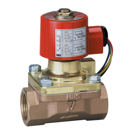
1.Overview The DP-10 series are compact, Pilot-Operated and Piston type high reliability solenoid valves featuring wide application for such various as steam, air, water and oil. And also wide products variation for such various requirements as AC/DC voltage, normally closed/opened and brass/stainless made. -
Page 3: 3.Dimensions & Weight
3.Dimensions & Weight ■DP-10/15 ■DP-10D/15D (DP-15: 15-10A) (DP-15: 15-50A) (mm) Wight (kg) Nominal Size DP-10/15 DP-10D/15D DP-10/15 DP-10D/15D Rc 3/8 14.5 Rc 1/2 14.5 Rc 3/4 17.5 Rc 1 21.0 Rc 1 1/4 26.0 Rc 1 1/2 29.5 Rc 2 36.5 ■DP-13/17 ■DP-13D/17D... - Page 4 ■DP-12/16 ■DP-12D/16D (DP-16: 15-50A) (DP-16D: 15-50A) (mm) Weight (kg) Nominal Size DP-12/16 DP-12D/16D DP-12/16 DP-12D/16D Rc 3/8 14.5 109.5 Rc 1/2 14.5 109.5 Rc 3/4 17.5 116.5 Rc 1 21.0 123.5 Rc 1 1/4 26.0 150.5 Rc 1 1/2 29.5 157.5 Rc 2 36.5...
-
Page 5: 4.Operation
4.Operation DP-10/13/15/17 DP-10D/13D/15D/17D * The structure differs slightly for DP-12/14/16/18/12D/14D/16D/18D. (1) Operation When the power is turned ON, the coil① is magnetized and the plunger③ is sucked up, thereby open the pilot valve④. The pressure at the upper part of the valve (diaphragm)⑧... -
Page 6: 5.Nominal Size Selection Method
5.Nominal Size Selection Method 5.1 Nominal Size Selection Chart ■Piston type (For steam) (DP-10/13/15/17/10D/13D/15D/17D) Nominal Size ・65A 【Example】 Under the following conditions, the appropriate nominal size would be determined as described below. Inlet pressure(P ): 0.7MPa; Outlet pressure(P ): 0.5MPa; Flow rate (W): 400kg/h. - Page 7 ■Piston type (For air) (DP-10/13/15/17/10D/13D/15D/17D) Nominal Size ・65A 【Example】 Under the following conditions, the appropriate nominal size would be determined as described bellow. Inlet pressure(P ): 0.4MPa; Outlet pressure(P ): 0.3MPa; Flow rate (Q) of air(20℃): 300m /h(Normal condition). First, find the point[A] where (P ) and ) intersect.
- Page 8 ■Piston type (For water) (DP-10/13/15/17/10D/13D/15D/17D) Nominal Size ・65A △P: Differential Pressure 【Example】 Under the following conditions, the appropriate nominal size would be determined as described bellow. Inlet pressure(P ): 0.5MPa; Outlet pressure(P ): 0.35MPa; Flow rate (V): 150L/min. First, find the point[A] where (V) and (Δ P) = (P ) - (P ).
- Page 9 ■Diaphragm type (For air) (DP-12/14/16/18/12D/14D/16D/18D) Nominal Size 【Example】 Under the following conditions, the appropriate nominal size would be determined as described bellow. Inlet pressure(P ): 0.5MPa; Outlet pressure(P ): 0.35MPa; Flow rate (Q) of air(20℃): 600m /h(Normal condition). First, find the point[A] where (P ) and (P intersect.
- Page 10 ■Diaphragm type (For water) (DP-12/14/16/18/12D/14D/16D/18D) Nominal Size △P: Differential Pressure 【Example】 Under the following conditions, the appropriate nominal size would be determined as described bellow. Inlet pressure(P ): 0.7MPa; Outlet pressure (P ): 0.5MPa; Flow rate (V): 300L/min. First, find the point[A] where (V) and (Δ P) = (P ) - (P ).
-
Page 11: 5.2 Calculating The Nominal Size
5.2 Calculating the Nominal Size ■Formula for Cv value calculation 《For steam》 《For air》 P P When When P > P > (273+t) G Cv = Cv = Δ P (P +P ) 2940 Δ P (P +P ) P P... -
Page 12: 6.2 Wiring Method
6.2 Wiring Method (1) Wiring differs according to the voltage, AC100V or 200V (AC110V or 220V/AC120 or 240V). Wire the coil according to the instruction on the label attached to the coil. In order to prevent faulty or erroneous wiring, especially wiring in a dark or narrow space, it is recommended that each of the lead wires be clearly identified with different colors that can be easily recognized. -
Page 13: 6.3 Warning & Caution For Installation
6.3 Warning & Caution for Installation Warning (1) When there is a risk of having life hazard, harming a body or property by the malfunction of the solenoid valve, please install the safety device which operates interception, opening, warnings on the basis of machinery or device. (2)... -
Page 14: 7.Operating Procedure
7.Operating Procedure 7.1 Warning & Caution for Operation Warning (1) Prior to letting the application in the system, make sure that all connecting part are properly connected and there is no danger when the application flows out of pipe end. * May result in burn when application blow out. -
Page 15: 8.Maintenance Procedure
8.Maintenance Procedure 8.1 Warning & Caution for Maintenance Warning (1) Carry out the disassembling and maintenance only after confirming that no power is supplied. * May cause an electric shock. (2) Completely discharge internal pressure from the valves, lines, and cool the valves down to a level where you can touch it with bare hands disassembly and inspection. -
Page 16: 8.2 Troubleshooting
8.2 Troubleshooting Problem Cause Countermeasure Power is not turned ON. Check and turn on the power. Plunger P is stuck by foreign matter of Disassemble and remove the foreign the piping. matter. Be sure that the sliding action is smooth. Sliding action of plunger P is not smooth Replace upper parts. -
Page 17: 8.4 Disassembly Drawing
8.4 Disassembly Drawing ■DP-10/15/10D/15D DP-13/13D is shell flange type. DP-17/17D is welded flange type. Model: DP-10D/13D/15D/17D Hexagon nut Kick Spring Wave washer Plain washer Plunger P Name Plate O-ring Model: DP-10/13/15/17 Plunger P Coil Valve spring (20-65A * 65A is for DP-13/13D only. O-ring Coupling spring Pilot ring... - Page 18 ■DP-12/16/12D/16D DP-14/14D is shell flange type. DP-18/18D is welded flange type. Hexagon nut Wave washer Plain washer Name Plate O-ring Rubber bush Plain washer Coil Lead wire ground O-ring Pipe 10-25A Pipe 32-50A Hexagon headed bolt Hexagon Spring Washer headed bolt Spring Washer Cover 10-40A Cover 50A...
- Page 19 Fire, flood, earthquake, thunder and other natural disasters. Consumable parts such as O-ring, gasket, diaphragm and etc. Yoshitake is not liable for any damage or loss caused by malfunction or defect of the product. INTERNATIONAL DEPT. 955-5, Miyamae, Irukadeshinden, Komaki, Aichi, 485-0084, Japan...
Need help?
Do you have a question about the DP-10 Series and is the answer not in the manual?
Questions and answers