Table of Contents
Advertisement
Quick Links
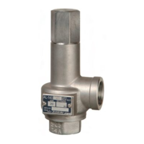
MODEL AL-150 series and AL-140 series
SAFETY RELIEF VALVE
Thank you very much for choosing the Yoshitake's product. To ensure the correct and safe use of the product,
please read this manual before use. This manual shall be kept with care for future references.
The symbols used in this manual have the following meanings.
1. Usage of the Product ·················································· 1
2. Specifications···························································· 1
3. Dimensions and Weight ··············································· 2
4. Structure ································································ 3
5. Operation ······························································· 4
6. Nominal Size Selection Table ········································ 4
7. Installation ································································ 7
8. Maintenance ····························································· 8
Warranty Information
PRODUCT MANUAL
This symbol indicates a potentially hazardous situation that, if not avoided,
could result in death or serious injury.
This symbol indicates a hazardous situation that, if not avoided, may result in
minor or moderate injury or may result in only property damage.
6.1 For steam (at saturated temperature) ························ 4
6.2 For air (at 20˚C) ··················································· 5
6.3 For water (accumulation: 25%) ································ 6
7.1 Piping example ···················································· 8
8.1 Daily inspection ··················································· 9
8.2 Monthly inspection ··············································· 9
8.3 Troubleshooting ··················································· 9
Table of Contents
.
E PDT-180c
■
■
Advertisement
Table of Contents

Related Manuals for Yoshitake AL-150 Series


Summary of Contents for Yoshitake AL-150 Series
-
Page 1: Table Of Contents
SAFETY RELIEF VALVE PRODUCT MANUAL Thank you very much for choosing the Yoshitake’s product. To ensure the correct and safe use of the product, please read this manual before use. This manual shall be kept with care for future references. -
Page 2: Warning
1. Usage of the Product The AL-150 series and the AL-140 series safety relief valves are used mainly in various pressure vessels, instrumentation devices and at outlet of pressure reducing valves to prevent accidents caused by abnormal pressure rise. 2. Specifications... -
Page 3: Dimensions And Weight
3. Dimensions and Weight AL-150L AL-150H, AL-140H AL-140ML AL-150, AL-140 Fig.1 Dimensions ■ AL-150, 150L Dimensions [mm] Weight Blowout [kg] Nominal area size AL-150 AL-150L AL-150 AL-150L 20.1 Rc 1/2 34.6 Rc 3/4 128.5 53.0 Rc 1 51.5 144.5 93.3 Rc 1 1/4 61.5 181.5 135.2 Rc 1 1/2... -
Page 4: Structure
■ AL-150H, 140H Dimensions [mm] Blowout area Weight [kg] Nominal size di × do AL-140H AL-150H AL-140H AL-150H AL-140H AL-150H AL-140H AL-150H 20.1 22.9 Rc 1/2 × Rc 3/4 126.5 34.6 39.5 Rc 3/4 × Rc 1 130.5 53.0 60.6 Rc 1 ×... -
Page 5: Operation
5. Operation Blowout operation As the inlet pressure approaches the blowout pressure, the force of fluid pushing up the valve [3] approaches the force of the spring [5] pressing down the valve [3]. The safety relief valve commences to blow when the inlet pressure reaches around 3% below the blowout pressure. The fluid accumulates gradually on the pressure groove [18] and when the fluid pressure reaches the blowout pressure the valve [3] pops. -
Page 6: For Air (At 20˚C)
6.2 For air (at 20˚C) 6.2.1 AL-150, AL-140, AL-140ML and AL-150L Capacity <Pressure vessel structure standard> [kg/h] Blowout Set pressure [MPa] Nominal area size 0.05 20.1 34.6 53.0 93.3 135.2 1093 1203 208.2 1006 1176 1346 1516 1687 1857 6.2.2 AL-140H Capacity <Pressure vessel structure standard>... -
Page 7: For Water (Accumulation: 25%)
6.3 For water (accumulation: 25% *1) 6.3.1 AL-150, AL-140 and AL-140ML Capacity <Yoshitake standard> Blowout Set pressure [MPa] Nominal area size 0.05 20.1 34.6 53.0 93.3 10.0 135.2 10.3 11.3 12.2 13.0 13.8 14.6 208.2 10.0 12.3 14.2 15.9 17.4 18.8... -
Page 8: Installation
7. Installation Warning 1. Do not install any closing device such as a stop valve at inlet or outlet sides of the product. * Failure to follow this notice may result in damage to the pressure vessel because such closing device may hamper the blowout of the safety relief valve. -
Page 9: Piping Example
Pipe mount 1. Pipe mount should have sufficient strength and rigidity against stress which are induced by reaction force in opposite direction of the exhaust through the axis of the exhaust pipe. 2. Pressure loss in pipe mount leads to decrease in the discharge volume and to unstable operation of the product. -
Page 10: Daily Inspection
8.1 Daily inspection Check the following items while the system is in operation. • Corrosion or crack on the product • Leakage from the product under normal working pressure (check it visually and aurally). • Leakage from joints between the product and piping. * Please contact us if any abnormal condition is observed. - Page 11 The product is installed at outlet 4. The pressure reducing valve needs to be repaired. If it is Yoshitake’s product, side of pressure reducing valve please contact us. which is out of order, and the reduced pressure of the valve is getting higher than expected.
Need help?
Do you have a question about the AL-150 Series and is the answer not in the manual?
Questions and answers