Table of Contents
Advertisement
Quick Links
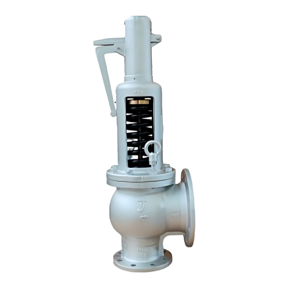
FULL BORE SAFETY VALVE
Thank you very much for choosing the Yoshitake's product. To ensure the correct and safe use of the
product, please read this manual before use. This manual shall be kept with care for future references.
The symbols used in this manual have the following meanings.
Warning
Caution
1. Specifications ···························································· 1
2. Dimensions and structure ············································ 2
3. Operation ······························································· 3
4. Nominal size selection table ········································· 4
5. Installation ······························································ 5
6. Precautions for use ···················································· 7
7. Maintenance ····························································· 8
7.1 Daily inspection ··················································· 8
7.2 Periodic inspection ··············································· 8
7.3 Troubleshooting ··················································· 9
MODEL AF-10EN
PRODUCT MANUAL
This symbol indicates a potentially hazardous situation that, if not avoided, may
result in death or serious injury.
This symbol indicates a potentially hazardous situation that, if not avoided, may
result in minor or moderate injury or may result in only property damage.
Table of Contents
.
■EPDT-395■
Advertisement
Table of Contents

Subscribe to Our Youtube Channel
Related Manuals for Yoshitake AF-10EN


Summary of Contents for Yoshitake AF-10EN
-
Page 1: Table Of Contents
FULL BORE SAFETY VALVE PRODUCT MANUAL Thank you very much for choosing the Yoshitake’s product. To ensure the correct and safe use of the product, please read this manual before use. This manual shall be kept with care for future references. -
Page 2: Specifications
1. Specifications Model AF-10EN Structure Open type with lever Nominal size 20A-100A Application Steam, Air, Other non-dangerous gases Working pressure 0.1-1.6 MPa Max. temperature 250 °C Body Ductile cast iron Material Spring chamber Ductile cast iron Valve and Valve seat... -
Page 3: Dimensions And Structure
2. Dimensions and structure Figure 1 Name of Parts Name of Parts Body Spindle B Spring Chamber Spring Adjusting Screw Lever 13,14 Stud Bolt Valve Hexagon Nut Valve Seat Square Head Plug Valve Cover Name Plate Guide Plate Lever Support Spindle A Eye Nut ■EPDT-395■... -
Page 4: Operation
(mm) Nominal Flow area size 18.5 29.5 36.5 1046 1661 59.5 2780 4185 100A 6503 3. Operation 1. Initial closed state The valve is closed by the spring force while the inlet pressure is lower than the set pressure. 2. Start to discharge As the inlet pressure increases, the force pushing up the valve becomes closer to the spring force pushing down the valve, and the product starts to discharge. -
Page 5: Nominal Size Selection Table
4. Nominal size selection table ●For Steam (Saturated steam temperature) EN ISO 4126-1:2013 (kg/h) Pressure (MPa) Nominal size 1010 1047 1219 1392 1564 1151 1437 1723 2007 2291 2574 1321 1762 2202 2639 3074 3509 3942 1393 2098 2799 3497 4191 4882 5572... -
Page 6: Installation
5. Installation Warning 1. Do not install any closing device such as a stop valve at the inlet or outlet side of the product. * Failure to follow this notice may result in damage to equipment due to insufficient discharge caused by resistance from the closing device. - Page 7 Pipe mount 1.1 The pipe mount should have adequate strength to endure the reaction force, which is applied toward the opposite direction of the discharge and along with the center line of the discharge port. 1.2 Pressure loss in the pipe mount decreases the discharge capacity and destabilize the product operation.
-
Page 8: Precautions For Use
6. Precaution for use Warning 1. Do not touch the product, pipes, or the lever [4] with bare hands. * Failure to follow this notice may result in scalds or injury in case that the fluid is hot. 2. Wear earplugs when checking the operation of the product, and do not stand in front of the discharge pipe. -
Page 9: Maintenance
7. Maintenance Warning 1. Do not touch the product, pipes, or the lever [4] with bare hands. * Failure to follow this notice may result in scalds or injury in case that the fluid is hot. 2. Wear earplugs when checking the operation of the product, and do not stand in front of the discharge pipe. -
Page 10: Troubleshooting
(readjusted) or the normal working pressure needs to be lowered. The product needs to be returned to Yoshitake to raise (readjust) the set pressure. 5. Difference between the set pressure 5. The product needs to be returned and the normal working pressure is to Yoshitake. - Page 11 4. The product is installed at outlet side of 4. The pressure reducing valve pressure reducing valve which is out of needs repair. If it is Yoshitake’s, order, and the reduced pressure of the please contact us. valve is getting higher than expected.
-
Page 12: Warranty Information
( e.g. in case of corrosion due to outdoor use). Fire, flood, earthquake, thunder and other natural disasters. Consumable parts such as O-ring, gasket, diaphragm and etc. Yoshitake is not liable for any damage or loss caused by malfunction or defect of the product. PDD-046f...
Need help?
Do you have a question about the AF-10EN and is the answer not in the manual?
Questions and answers