Table of Contents
Advertisement
Quick Links
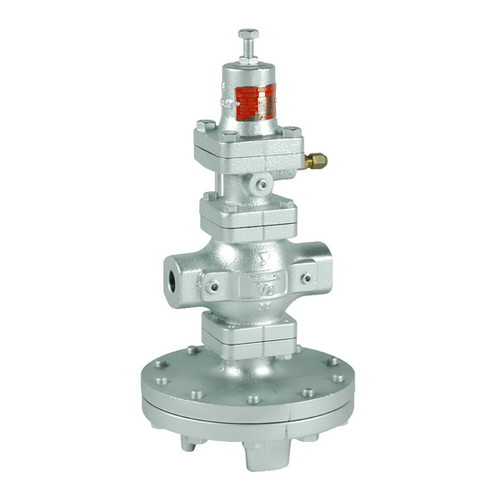
PRESSURE REDUCING VALVE
Installation & Operation Manual
Please read this bulletin thoroughly before using the pressure reducing valve, so that you may
do so correctly and safely. Please carefully store this bulletin in a handy place.
---------The following safety symbols are used in this manual. --------
Warning
This symbol indicates a potentially hazardous situation that, if not
avoided, could result in death or serious injury.
This symbol indicates a hazardous situation that, if not avoided, may
Caution
result in minor or moderate injury. ("Caution" may also be used to
indicate other unsafe practices or risks of property damage.)
1. Features ····································································· 1
2. Specifications ······························································· 1
3. Dimensions and Weights ················································ 2
4. Operation ···································································· 3
5.1 Specifications selection chart ······································ 7
5.2 Safety valve setting pressure chart ······························· 7
5.3 Characteristics chart ················································· 7
5.4 Nominal size selection chart ······································· 8
5.5 Nominal size selection calculation formula ····················· 9
6.1 Example of piping ····················································· 9
6.2 Precautions during installation ···································· 10
6.3 Installing accessories ··············································· 11
6.4 Sensing pipe connection method ································ 11
7.1 Precautions during operation ····································· 11
7.2 Adjustment procedures ············································· 12
8.1 Troubleshooting ······················································ 12
8.2 Precautions during maintenance and inspection ············· 13
8.3 Disassembly ··························································· 14
8.4 Precautions during reassembly ··································· 14
8.5 Exploded drawing ···················································· 15,16
After Sale Service
Model GP-2000
Contents
■EPDT-014f■
Advertisement
Table of Contents

Related Manuals for Yoshitake GP-2000


Summary of Contents for Yoshitake GP-2000
-
Page 1: Table Of Contents
Model GP-2000 PRESSURE REDUCING VALVE Installation & Operation Manual Please read this bulletin thoroughly before using the pressure reducing valve, so that you may do so correctly and safely. Please carefully store this bulletin in a handy place. ―――――――――The following safety symbols are used in this manual. ――――――――... -
Page 2: Features
1. Features GP-2000 pressure reducing valves for steam are pilot-operated valves which can be used with confidence for small to large flow rate, in a host of applications ranging from building utilities systems, air-conditioning systems, and factory systems, etc. 2. Specifications 2.1 Models... -
Page 3: Dimensions And Weights
3. Dimensions and Weights 3-1. GP-2000 (Integral mount type) • The structure differs for nominal sizes 50A to 100A. (Flanged) (Screw) (㎜) Screw (JIS Rc) Flanged (JIS 20KRF) Size Weight Weight L H H A L H H A 1... - Page 4 • The structure differs for nominal sizes 50A to 100A. Screw (JIS Rc) (㎜) Weight L H H A Size 1 (kg) Rc 1/2 15.5 Rc 3/4 15.5 Rc 1 20.0 Rc 1-1/4 23.0 Rc 1-1/2 23.0 Rc 2 34.0 Flanged (JIS 20KRF)...
-
Page 5: Operation
4. Operation The pressure reducing valve reduces pressure by the throttling the valve. The valve is composed of the main valve and main valve seat for throttling, and adjusting spring, diaphragm, pilot valve, and piston for pressure sensing and activation. Parts name Body Main Valve... - Page 6 (2) Turing adjusting screw [27] clockwise compresses the spring, which flexes pilot diaphragm [23] to open the pilot valve. The fluid passing through pilot valve [17] and pilot valve seat [18] enters the main diaphragm chamber via pipes A [34] and C [36]. This fluid also flows to the reduced side of the body [1] through pipe B [35] and the orifice of joint B [31] that connects to the body.
- Page 7 (4) Reduced pressure is led to the pilot diaphragm chamber [23]-1 via the sensing pipe and reduced pressure sensing port [56]. The pilot diaphragm receives the reduced pressure to be balanced with the spring load. The pilot valve travel is controlled by the spring load and pressure applied to the pilot diaphragm due to variations in reduced pressure.
-
Page 8: Nominal Size Selection Method
5. Nominal Size Selection Method 5.1 Pressure reducing valve specification selection chart Refer to the above selection chart to select the most appropriate pressure reducing valve. Find the point of intersection of inlet pressure (P ) and reduced pressure ). When the point of intersection is within range (A), reduce pressure in two stages. -
Page 9: Nominal Size Selection Chart
5.4 Nominal size selection chart For example, take a pressure reducing valve whose inlet pressure (P ) is 0.6 MPa, reduced pressure (P ) 0.4 MPa, flow rate 600 kg/h. When determining the nominal size, find the point of intersection (A) of inlet pressure 0.6 MPa and reduced pressure 0.4 MPa. Vertically proceed from point (A) to come across the flow rate 600 kg/h, and regard this point as (B). -
Page 10: Nominal Size Selection Calculation Formula
----- *Please consults factory for internal sensing method valves. [Flow rate calculation example of GP-2000 pressure reducing valve] The flow rate of the pressure reducing valve is calculated under the following conditions: Nominal size 15A, saturated steam, Inlet pressure of 0.6 MPa, Reduced pressure of 0.4 MPa. -
Page 11: Precautions During Installation
6.2 Precautions during installation Warning (1) Because of heavy weight, hold the valve with lifting equipment while piping. Refer to “3. Dimensions and weights” table for the valve weight. ※Failure to do so may result in injury due to dropping the valve. (2) In case installing safety valve as safety device at outlet side, joint relief pipe at outlet of safety valve and guide it to safety place where steam can relief out. -
Page 12: Installing Accessories
6.3 Installing accessories Warning (1) When installing the pressure reducing valve, be sure to connect the provided sensing pipe and joint. ※Unless the sensing pipe is connected, the valve will not operate. Further, steam may blow off, resulting burns. 6.4 Sensing pipe connection method Connect the provided sensing pipe (φ8-2m) and joint ( φ... -
Page 13: Adjustment Procedures
7.2 Adjustment Follow the steps below, and slowly turn the adjusting screw to set pressure. Incorrect adjustment may cause hunting, water hammer, etc., resulting in damage to the valve and other equipment. ( See 6.1 Example of piping .) Check that all stop valves (V to V ) are closed. -
Page 14: Precautions During Maintenance And Inspection
Problem Cause Solution 2. Foreign matter exists between 2. Disassemble pilot valve pilot valve and pilot valve seat, or as-sembly, and clean or replace it. scratches exist. 3. Orifice of tee is clogged. 3. Remove the orifice and clean it. Reduced pressure 4.... -
Page 15: Disassembly
(6)Remove condensate completely from the line, and close the stop valves before and after the valve when not using it for long periods of times. ※Rust generated in the valves and lines may cause malfunction. (7)In case of no operation for a long period of time, perform operating exam before start operation again. -
Page 16: Exploded Drawing
8.5 Exploded drawing For size 65A to 200A, refer to P.16 ■EPDT-014f■ -15-... - Page 17 65A to 200A Parts within the flame are consumable. Please contact us for purchase of these consumable parts. Note (*1): Apply a liquid sealant for heat and steam resistant (Recommendation: SOLVEST 110) to the sealing surface of the diaphragm bottom and the top cover. (*2): For size 15A to 125A, attach the tee with turning upward the slit part.
Need help?
Do you have a question about the GP-2000 and is the answer not in the manual?
Questions and answers