
Related Manuals for Smarteh LPC-2.PW1


Summary of Contents for Smarteh LPC-2.PW1
- Page 1 USER MANUAL Longo programmable controller LPC-2.PW1 4 Channel PWM Signal Output module Version 2 SMARTEH d.o.o. / Poljubinj 114 / 5220 Tolmin / Slovenia / Tel.: +386(0) 388 44 00 / e-mail: info@smarteh.si / www.smarteh.si...
- Page 2 Longo programmable controller LPC-2.PW1 Written by SMARTEH d.o.o. Copyright © 2018, SMARTEH d.o.o. User Manual Document Version: 2 January, 2018...
- Page 3 24 months is valid from the date of sale to the end buyer, but not more than 36 months after delivery from Smarteh. In case of claims within warranty time, which are based on material malfunctions the producer offers free replacement. The method of return of malfunctioned module, together with description, can be arranged with our authorized representative.
-
Page 4: Table Of Contents
Longo programmable controller LPC-2.PW1 Longo programmable controller LPC-2.PW1 1 ABBREVIATIONS................1 2 DESCRIPTION...................2 3 FEATURES..................3 4 OPERATION..................4 4.1 Parameters................4 4.2 Output waveform for output setting 0% and 100%........5 5 INSTALLATION..................6 5.1 Connection scheme..............6 5.2 Mounting instructions..............8 5.3 Module labeling...............10 6 TECHNICAL SPECIFICATIONS..............11 7 SPARE PARTS..................12... -
Page 5: Abbreviations
Longo programmable controller LPC-2.PW1 1 ABBREVIATIONS Light emitting diode Pulse width modulation... -
Page 6: Description
Longo programmable controller LPC-2.PW1 2 DESCRIPTION LPC-2.PW1 is a 4 channel PWM signal output module. Its main field of application is controlling PWM dimmable ballasts in lighting system. LEDs indicate state of signal present on corresponding module output. Their brightness corresponds to the output setting 0 .. -
Page 7: Features
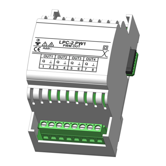
Longo programmable controller LPC-2.PW1 3 FEATURES Figure 1: LPC-2.PW1 module Table 1: Features 4 channel PWM signal output Galvanic isolated outputs 100 mA per output with overload protection Push-pull transistor outputs capable of driving the signal over up to 100 nF capacitance on the lines. -
Page 8: Operation
Longo programmable controller LPC-2.PW1 4 OPERATION Module parameters can be read or written via Smarteh IDE software. 4.1 Parameters If parameter is set to logical “1”, is considered to be active, enabled or set. If parameter has logical value “0” is considered to be inactive, disabled or cleared. -
Page 9: Output Waveform For Output Setting 0% And 100
Longo programmable controller LPC-2.PW1 4.2 Output waveform for output setting 0% and 100% Figure 2: Output waveform for output setting 0% and 100%... -
Page 10: Installation
Longo programmable controller LPC-2.PW1 5 INSTALLATION 5.1 Connection scheme Figure 3: Connection scheme Outputs must not be connected together. - Page 11 Longo programmable controller LPC-2.PW1 Table 2: OUT OUT1.1 PWM output OUT1.2 OUT2.3 PWM output OUT2.4 OUT3.5 PWM output OUT3.6 OUT4.7 PWM output OUT4.8 Table 3: K1 Internal BUS Data & DC power supply Connection to I/O module Table 4: K2 Internal BUS Data &...
-
Page 12: Mounting Instructions
Mounting instructions: 1. Switch off main power supply. 2. Mount LPC-2.PW1 module to the provided place inside an electrical panel (DIN EN50022-35 rail mounting). 3. Mount other LPC-2 modules (if required). Mount each module to the DIN rail first, then attach modules together through K1 and K2 connectors. - Page 13 Longo programmable controller LPC-2.PW1 Figure 5: Minimum clearances The clearances above must be considered before module mounting.
-
Page 14: Module Labeling
01 – year of production. • Label 2 description: 1. S/N:PW1-S9-1700000002 is the serial number. PW1 – short product name, • S9 – user code (test procedure, e.g. Smarteh person xxx), • 17000000002 – year and current stack code, • 17 – year, •... -
Page 15: Technical Specifications
Longo programmable controller LPC-2.PW1 6 TECHNICAL SPECIFICATIONS Table 6: Technical specifications Power supply from internal BUS Power consumption Output voltage in "high" state 11 V ±10 % @ load current 0 .. 100 mA Load current per channel max. 100 mA... -
Page 16: Spare Parts
Longo programmable controller LPC-2.PW1 7 SPARE PARTS For ordering spare parts following Part Numbers should be used: LPC-2.PW1, 4 Channel PWM Signal Output module LPC-2.PW1 P/N: 225PW117001001... -
Page 17: Changes
Longo programmable controller LPC-2.PW1 8 CHANGES The following table describes all the changes to the document. Date Description 15.01.18 Technical update. Page 7, 11. 15.11.17 The initial version, issued as LPC-2.PW1 module UserManual. -
Page 18: Notes
Longo programmable controller LPC-2.PW1 9 NOTES...
Need help?
Do you have a question about the LPC-2.PW1 and is the answer not in the manual?
Questions and answers