Sign In
Upload
Manuals
Brands
ST Manuals
Motherboard
STEVAL-IHM015V1
User Manuals: ST STEVAL-IHM015V1 Motor Control Tool
Manuals and User Guides for ST STEVAL-IHM015V1 Motor Control Tool. We have
1
ST STEVAL-IHM015V1 Motor Control Tool manual available for free PDF download: User Manual
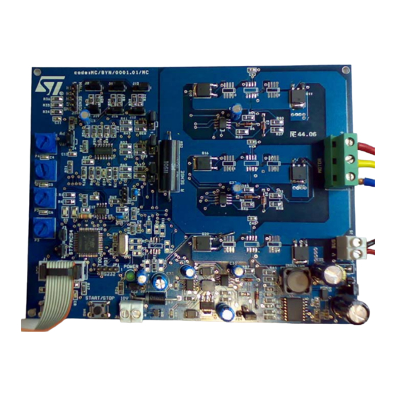
ST STEVAL-IHM015V1 User Manual (53 pages)
Low voltage motor control demonstration board based on ST7MC MCU
Brand:
ST
| Category:
Motherboard
| Size: 0 MB
Table of Contents
Table of Contents
2
System Architecture
7
Figure 2. Motor Control System Architecture
7
Safety and Operating Instructions
8
General
8
Intended Use of the Demonstration Board
8
Installing the Demonstration Board
8
Electronic Connections
8
Operating the Demonstration Board
9
ST7FMC2S4T6 Microcontroller Functions
10
Main Features
10
Table 1
11
ST7FMC2S4T6 Functions
11
STS8DNH3LL Characteristics
12
Table 2. STS8DNH3LL Absolute Maximum Ratings
12
Electrical Characteristics of the Board
13
Table 3. Electrical Characteristics of the Control Board
13
Figure 1. STEVAL-IHM015V1
13
Board Architecture
14
Figure 4. Board Architecture
14
Power Supply
15
Power Stage
15
Table 4. Power Supply Jumper Settings
15
Figure 5. Power Supply Architecture
15
Table 5
16
Compatible Devices
16
Figure 3. STS8DNH3LL
16
ICC Connector
17
Figure 7. Board Layout
17
Figure 8. ICC Connector
17
SDI Interface (Serial Data Interface)
18
Figure 9. SDI Connector
18
Board Schematic
19
Figure 10. Board Schematic: Control Block
19
Figure 11. Board Schematic: Power Block
20
Motor Control Operations
21
Environmental Considerations
21
Hardware Requirements
21
Software Requirements
22
Installing the Software
22
Board Setup
23
Choosing the Right Firmware
23
Table 6. Firmware Libraries Arranged According to Driving Strategy
23
Figure 12. STVD7 for Indart-STX Toolset Configuration
23
Configuring the Firmware Using the GUI
24
Motor Type Selection
24
Table 7. ".H" Configuration Files
24
3-Phase BLAC/DC (Trapezoidal)" Settings
25
Figure 13. Motor Type Choice Window
25
Figure 14. "3-Phase BLAC/DC (Trapezoidal)" Basic Parameters Window
25
Table 8
26
3-Phase BLAC/DC (Trapezoidal)" Advanced Settings
27
Table 8. "3-Phase BLAC/DC (Trapezoidal)" Basic Parameters
27
Figure 15. "3-Phase BLAC/DC (Trapezoidal)" Advanced Parameters Window
27
3-Phase BLAC/DC (Trapezoidal)" Advanced Parameters
28
3-Phase PMAC Motor (Sinewave)" Settings
29
Figure 16. "3-Phase PMAC Motor (Sinewave)" Basic Parameters Window
29
3-Phase PMAC Motor (Sinewave)" Advanced Settings
31
Table 11. "3-Phase PMAC Motor (Sinewave)" Advanced Parameters
31
Figure 17. "3-Phase PMAC Motor (Sinewave)" Advanced Parameters Window
31
Changing the Maximum Current Allowed by GUI
32
Compiling the Firmware
32
Figure 18. ST7VD Active Project Configuration
32
Programming the Firmware
33
Figure 19. System Setup for Programming Phase
33
Setting the Option Bytes
34
Figure 20. Option Byte Settings
34
Figure 21. Programming Option Auto Window
34
Configuring the DC Input Range
35
Jumper Settings Table
35
Board Connection
35
Table 12. Jumper Settings Table
35
Changing the Maximum Allowed Bus Voltage Level
36
Table 13. Bus Voltage Threshold Parameter
36
Figure 22. System Setup for Running Phase
36
Changing the Maximum Allowed Current Level
37
Driving the BLDC Motor (Trapezoidal - Sensorless)
38
Specific Connection (Sensor)
38
Specific Jumper Settings
38
LED Action after Power-On
38
Setting the Potentiometers
38
Table 14. BLDC SL Jumpers Setting
38
Running the Motor (LED Action)
39
Changing the Real-Time Parameters
39
Stopping the Motor (LED Action)
40
Configuring the System for BEMF Amplification
40
Detecting the BEMF During the PWM on Time
40
Table 16. BLDC SL with BEMF Amplification Jumper Settings
40
Detecting the BEMF Using the Internal Reference
41
Detecting the BEMF Using the External Reference Vbus/2
41
Detecting the BEMF Using the External Reference and Reconstructed
41
Neutral Point of the Motor
41
Driving the BLDC Motor (Trapezoidal - Sensored)
42
Specific Sensor Connections
42
Specific Jumper Settings
42
Table 17. "BLDC Sensored" Motor Connections
42
Table 18. BLDC SR Jumper Settings
42
LED Action after Power-On
43
Setting the Potentiometers
43
Running the Motor (LED Action)
43
Changing the Real-Time Parameters
43
Table 19. Potentiometer Functionality Based on Open/Closed Loop Driving Strategy
43
Stopping the Motor (LED Action)
44
Driving the BLAC Motor
44
Specific Sensor Connections
44
Table 20. "PMAC Sensored" Motor Connections
44
Specific Jumper Settings
45
LED Action after Power-On
45
Table 21. PMAC SR Jumper Settings
45
Table 22. Potentiometer Functionality Based on an Open-/Closed-Loop Driving Strategy
46
Table 23. Bill of Materials
47
Table 24. Document Revision History
52
Advertisement
Advertisement
Related Products
ST STEVAL-IHP007V1
ST STEVAL-IHM020V1
ST STEVAL-IHM010V1
ST STEVAL-IHM022V1
ST STEVAL-IHM011V1
ST STEVAL-IHM031V1
ST STEVAL-IME015V1
ST STEVAL-IDB008V1M
ST STEVAL-ISB041V1
ST STEVAL-IDB011V1
ST Categories
Motherboard
Computer Hardware
Microcontrollers
Control Unit
Controller
More ST Manuals
Login
Sign In
OR
Sign in with Facebook
Sign in with Google
Upload manual
Upload from disk
Upload from URL