Table of Contents
Advertisement
Quick Links
Chipsmall Limited consists of a professional team with an average of over 10 year of expertise in the distribution
of electronic components. Based in Hongkong, we have already established firm and mutual-benefit business
relationships with customers from,Europe,America and south Asia,supplying obsolete and hard-to-find components
to meet their specific needs.
With the principle of "Quality Parts,Customers Priority,Honest Operation,and Considerate Service",our business
mainly focus on the distribution of electronic components. Line cards we deal with include
Microchip,ALPS,ROHM,Xilinx,Pulse,ON,Everlight and Freescale. Main products comprise
IC,Modules,Potentiometer,IC Socket,Relay,Connector.Our parts cover such applications as commercial,industrial,
and automotives areas.
We are looking forward to setting up business relationship with you and hope to provide you with the best service
and solution. Let us make a better world for our industry!
Contact us
Tel: +86-755-8981 8866 Fax: +86-755-8427 6832
Email & Skype: info@chipsmall.com Web: www.chipsmall.com
Address: A1208, Overseas Decoration Building, #122 Zhenhua RD., Futian, Shenzhen, China
Advertisement
Table of Contents

Related Manuals for ST STEVAL-ISB041V1


Summary of Contents for ST STEVAL-ISB041V1
- Page 1 Chipsmall Limited consists of a professional team with an average of over 10 year of expertise in the distribution of electronic components. Based in Hongkong, we have already established firm and mutual-benefit business relationships with customers from,Europe,America and south Asia,supplying obsolete and hard-to-find components to meet their specific needs.
-
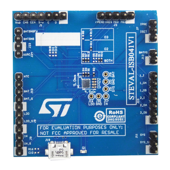
Page 2: Figure 1: Steval-Isb041V1 Evaluation Board
STBC02 Introduction The STEVAL-ISB041V1 evaluation board is based on STBC02 Li-Ion and Li-Po linear battery management device, integrating a CC-CV charger algorithm, an always-on LDO, smart-reset Watchdog, a protection circuit module (PCM) and a dual SPDT switch matrix. -
Page 3: Table Of Contents
Contents UM2185 Contents Getting started ................. 5 Board overview ................. 5 Input/output connectors ..............5 Test procedure and technical recommendations ....... 7 1.3.1 Recommended equipment ..............7 1.3.2 Procedure to test a typical full charging cycle ........8 GND pins ..................10 Schematic diagram ................ - Page 4 UM2185 List of tables List of tables Table 1: Input/output connector: pin description ..................5 Table 2: STEVAL-ISB041V1 evaluation board pin functions ..............10 Table 3: Ball description..........................17 Table 4: Document revision history ......................19 DocID030421 Rev 1 3/21...
- Page 5 Figure 3: STBC02 battery proper connection and routing ................ 11 Figure 4: Hall current probe ........................12 Figure 5: STEVAL-ISB041V1 circuit schematic ..................14 Figure 6: STEVAL-ISB041V1 PCB layout: top side .................. 15 Figure 7: STEVAL-ISB041V1 PCB layout: bottom side ................15 Figure 8: STBC02 block diagram ......................16 Figure 9: STBC02 (flipchip30, 2.25 mm x 2.59 mm package): ballout, top view ........
-
Page 6: Getting Started
UM2185 Getting started Getting started Board overview The STEVAL-ISB041V1 evaluation board size is 50 mm x 50 mm. The PCB is made by using FR4 glass epoxy support with 4 copper layers. The device features: Charges single-cell Li-Ion/Li-Po batteries with CC-CV algorithm and charge termination ... - Page 7 Getting started UM2185 Connector Symbol Signal name Pin description number Pre-charge current IPRE IPRE programming resistor LDO output LDO_S LDO output sensing Input supply voltage Input supply voltage IN_S sensing BAT_S Battery sensing Battery - positive terminal ---- ---- Reserved Battery temperature monitor pin System output...
-
Page 8: Test Procedure And Technical Recommendations
UM2185 Getting started Figure 2: STEVAL-ISB041V1 evaluation board pinout Test procedure and technical recommendations STBC02 linear battery management IC is designed to manage the whole battery charging procedure, powering the system through the power path node output (SYS unregulated voltage rail) via a low quiescent linear regulator output. -
Page 9: Procedure To Test A Typical Full Charging Cycle
Getting started UM2185 1.3.2 Procedure to test a typical full charging cycle The three most important STBC02 functional modes are: battery mode: V valid range, system up and running, V invalid range; shutdown mode: device supplied by battery but in shutdown mode; ... - Page 10 UM2185 Getting started Disconnect and reconnect battery. SYS and LOD node are not supplied now, as the device is in shutdown mode. To enter battery mode, you have to pull WakeUp pin to VBAT level (to be precise, the WakeUp pin has to exceed 3.0 V level). DocID030421 Rev 1 9/21...
-
Page 11: Gnd Pins
All GND pins are connected by a dedicated metallic layer: the evaluation board GND routing strategy does not feature separated GND branches. The only exception is the battery negative terminal connection. Table 2: STEVAL-ISB041V1 evaluation board pin functions Name Function... -
Page 12: Figure 3: Stbc02 Battery Proper Connection And Routing
UM2185 GND pins Name Function SW2_OA Load switch SPDT2 output A SW2_OB Load switch SPDT2 output B Forcing: output pin dedicated to SYS loading SYS_S Sensing: to measure system voltage directly on C2 capacitor NTC is assembled on board (fixed value 10 kΩ, resistor R4). If real NTC use is requested, remove R4 and connect the real element between NTC node and GND. -
Page 13: Figure 4: Hall Current Probe
GND pins UM2185 Figure 4: Hall current probe Avoid connecting serial resistors between battery pack and device to measure current voltage drop. Battery protection STBC02 works well when the charger is plugged; battery protection is activated in case of fully discharged battery. Safety timers do not support abnormally long delay between BAT node rise (protection stimulation) and protection deactivation. - Page 14 UM2185 GND pins WakeUp input internal pull-down: 500 k to GND tactile switch to battery (low to high transition) wakes up the device RESET circuit STBC02 is equipped with a multipurpose reset circuit. The mode can be selected by s-wire bus: ...
-
Page 15: Schematic Diagram
IPRE ISET BATSNSFV BATSNS IN_S LDO_S BATMS STBC02 10uF 1.0uF WURC WAK E_UP SW_SEL RST_PENDING ! DNP nRESET SW1_I RESET _NOW SYS_S SW1_OA SW1_OB SW2_I 1.0µF SW2_OA SW2_OB RESET_NOW RESET_NOW !DNP/10k 100k SW1_I RST_P ENDING SW1_I RST_P ENDING BAT_S SW1_OA nRESET SW1_OA nRESET... -
Page 16: Pcb Layout
UM2185 PCB layout PCB layout Figure 6: STEVAL-ISB041V1 PCB layout: top side Figure 7: STEVAL-ISB041V1 PCB layout: bottom side DocID030421 Rev 1 15/21... -
Page 17: Stbc02: Block Diagram And Ballout
STBC02: block diagram and ballout UM2185 STBC02: block diagram and ballout Figure 8: STBC02 block diagram Figure 9: STBC02 (flipchip30, 2.25 mm x 2.59 mm package): ballout, top view 16/21 DocID030421 Rev 1... -
Page 18: Table 3: Ball Description
UM2185 STBC02: block diagram and ballout Table 3: Ball description Alternative Bump name Description bump name Input supply voltage. Bypass this pin to ground with a E5-F5 2.2 µF capacitor Battery positive terminal. Bypass this pin to GND with A5-B5 a 4.7 µF ceramic capacitor System output. - Page 19 STBC02: block diagram and ballout UM2185 Alternative Bump name Description bump name Load switch SPDT2 output A SW2_OA (enabled/disabled PMOS) Load switch SPDT2 output B SW2_OB (enabled/disabled PMOS) C3-D3 Not connected 18/21 DocID030421 Rev 1...
-
Page 20: Revision History
UM2185 Revision history Revision history Table 4: Document revision history Date Version Changes 28-Mar-2017 Initial release. DocID030421 Rev 1 19/21... -
Page 21: Appendix A General Handling Precautions
UM2185 Appendix A General handling precautions Do not modify or manipulate the board and the device when the board is powered and/or connected to the load; Do not supply the board with a DC source higher than the device maximum voltage; ... - Page 22 ST products and/or to this document at any time without notice. Purchasers should obtain the latest relevant information on ST products before placing orders. ST products are sold pursuant to ST’s terms and conditions of sale in place at the time of order acknowledgement.
Need help?
Do you have a question about the STEVAL-ISB041V1 and is the answer not in the manual?
Questions and answers