Table of Contents
Advertisement
Quick Links
Advertisement
Table of Contents

Related Manuals for Supermicro B2SD2-8C-TF


Summary of Contents for Supermicro B2SD2-8C-TF
- Page 1 B2SD2-8C-TF B2SD2-12C-TF B2SD2-16C-TF B2SD1-8C-TF USER MANUAL Revision 1.0...
- Page 2 State of California, USA. The State of California, County of Santa Clara shall be the exclusive venue for the resolution of any such disputes. Supermicro's total liability for all claims will not exceed the price paid for the hardware product.
- Page 3 B2SD2(1)-8C/12C/16C-TF motherboard. About This Motherboard The Supermicro B2SD2(1)-8C/12C/16C-TF MicroBlade module motherboard supports an Intel® Xeon D-2100 SoC processor in a BGA package. The B2SD2-8C/12C/16C supports two CPU nodes on each board and B2SD1-8C-TF only supports one CPU node. The...
- Page 4 Super B2SD2(1)-8C/12C/16C-TF MicroBlade Module User's Manual Contacting Supermicro Headquarters Address: Super Micro Computer, Inc. 980 Rock Ave. San Jose, CA 95131 U.S.A. Tel: +1 (408) 503-8000 Fax: +1 (408) 503-8008 Email: marketing@supermicro.com (General Information) support@supermicro.com (Technical Support) Website: www.supermicro.com Europe Address: Super Micro Computer B.V.
-
Page 5: Table Of Contents
Preface Table of Contents Chapter 1 Introduction 1.1 Checklist ..........................8 Quick Reference .......................13 Quick Reference Table ......................14 Motherboard Features .......................15 1.2 Processor Overview ......................18 1.3 Special Features ........................18 Recovery from AC Power Loss ..................18 1.4 System Health Monitoring ....................19 Onboard Voltage Monitors ....................19 Fan Status Monitor with Firmware Control ...............19 System Resource Alert......................19 1.5 ACPI Features ........................20... - Page 6 Super B2SD2(1)-8C/12C/16C-TF MicroBlade Module User's Manual Chapter 3 Troubleshooting 3.1 Troubleshooting Procedures ....................37 Before Power On ......................37 No Power ..........................37 No Video ...........................37 System Boot Failure ......................38 Memory Errors ........................38 Losing the System's Setup Configuration .................39 When the System Becomes Unstable ................39 3.2 Technical Support Procedures ...................41 3.3 Frequently Asked Questions ....................42 3.4 Battery Removal and Installation ..................43...
- Page 7 Preface Appendix C Standardized Warning Statements Battery Handling ........................91 Product Disposal .......................93 Appendix D UEFI BIOS Recovery D.1 Overview ..........................94 D.2 Recovering the UEFI BIOS Image ..................94 D.3 Recovering the Main BIOS Block with a USB Device ............95...
-
Page 8: Chapter 1 Introduction
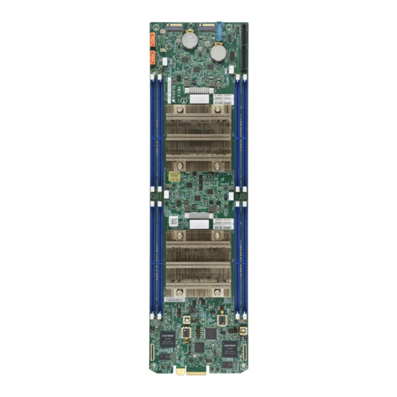
Introduction Congratulations on purchasing your computer motherboard from an acknowledged leader in the industry. Supermicro boards are designed with the utmost attention to detail to provide you with the highest standards in quality and performance. Please check that the following items have all been included with your motherboard. If anything listed here is damaged or missing, contact your retailer. - Page 9 Chapter 1: Introduction Figure 1-1. B2SD2-8C/12C/16C-TF Motherboard Image...
- Page 10 Super B2SD2(1)-8C/12C/16C-TF Microblade Module User's Manual Figure 1-2. B2SD1-8C-TF Motherboard Image...
- Page 11 Chapter 1: Introduction Figure 1-3. B2SD2-8C/12C/16C-TF Motherboard Layout (not drawn to scale) P2-LEDBMC LEDM2 P1-LEDBMC LEDM1 2500 P2-JPT1 2500 P2-JVRM1 TPM/PORT80 P1-JTPM1 P2-JTPM1 P1-JVRM1 TPM/PORT80 P1-JPT1 P1-JPT1:TPM 1-2:ENABLE 1-2:ENABLE 2-3:DISABLE 2-3:DISABLE P1-JWD1 P2-JWD1 WATCH DOG WATCH DOG 1-2:RST 1-2:RST P1_JBT1 2-3:NMI 2-3:NMI CMOS CLEAR...
- Page 12 Super B2SD2(1)-8C/12C/16C-TF Microblade Module User's Manual Figure 1-4. B2SD1-8C-TF Motherboard Layout (not drawn to scale) P1-LEDBMC LEDM1 TPM/PORT80 P1-JTPM1 P1-JVRM1 P1-JPT1 P1-JPT1:TPM 1-2:ENABLE 1-2:ENABLE 2-3:DISABLE 2-3:DISABLE P1-JWD1 P2-JWD1 WATCH DOG WATCH DOG 1-2:RST 1-2:RST P1_JBT1 2-3:NMI 2-3:NMI CMOS CLEAR BAR CODE P2-JPT1:TPM 1-2:ENABLE 2-3:DISABLE...
-
Page 13: Quick Reference
Chapter 1: Introduction Quick Reference POWER LEDM2 P2-LEDBMC LEDM2 LEDM1 P1-LEDBMC P2-JPT1 LEDM1 2500 P2-JVRM1 P1-JTPM1 P2-JPT1 2500 P2-JVRM1 P2-JTPM1 P1-JVRM1 TPM/PORT80 P1-JTPM1 P2-JWD1 P2-JTPM1 P1-JVRM1 TPM/PORT80 P1-JPT1 P1-JPT1 P1-JPME2 P1_JBT1 P1-DIMMB1 P1-JPT1:TPM 1-2:ENABLE 1-2:ENABLE 2-3:DISABLE 2-3:DISABLE P1-JWD1 P2-JWD1 WATCH DOG WATCH DOG 1-2:RST 1-2:RST... -
Page 14: Quick Reference Table
Super B2SD2(1)-8C/12C/16C-TF Microblade Module User's Manual Quick Reference Table Jumper Description Default Setting P1-JBT1 CMOS Clear for Node 1 Open (Normal) P2-JBT1 CMOS Clear for Node 2 Open (Normal) P1-JPME2 Manufacturing Mode for Node 1 Pins 1-2 (Normal) P2-JPME2 Manufacturing Mode for Node 2 Pins 1-2 (Normal) P1-JPT1 Onboard TPM Enable/Disable for Node 1... -
Page 15: Motherboard Features
Chapter 1: Introduction Motherboard Features Motherboard Features • Intel® Xeon D-2100 SoC (BGA Package) with a TDP of up to 100W Memory • Each of the two nodes supports up to 128GB of VLP RDIMM DDR4 memory with speeds of up to 2400MHz (sku dependent) DIMM Size •... - Page 16 Note 2: For IPMI configuration instructions, please refer to the Embedded IPMI Con- figuration User's Guide available at http://www.supermicro.com/support/manuals/. Note 3: If you purchase a Supermicro Out of Band (OOB) software license key (Supermicro P/N: SFT-OOB--LIC), please DO NOT change the IPMI MAC address.
- Page 17 Chapter 1: Introduction Figure 1-5. Chipset Block Diagram DDR4 1866/2133/2400 DDR4 1866/2133/2400 SoC 1 HDD backplane AOM-BPN-MS28US PE1[4:0] SATA GEN 3 Flexible I/O LAN1 Switch 1 SATA GEN 3 Flexible I/O LAN2 Switch 2 (Redundant) PCIE3.0 x4 Flexible I/O 21~18 B1SA4-F-KVM (debug only) CMM 2...
-
Page 18: Processor Overview
Super B2SD2(1)-8C/12C/16C-TF Microblade Module User's Manual 1.2 Processor Overview The Intel Xeon D-2100 series SoC processor family, with up to 16 cores and up to 100W of power, offers performance, reliability, and high intelligence. As a low-power system-on-a- chip motherboard, the B2SD2(1)-8C/12C/16C-TF is optimized for a variety of workloads that requires high compute power in a compact form-factor. -
Page 19: System Health Monitoring
Chapter 1: Introduction 1.4 System Health Monitoring The motherboard has an onboard Baseboard Management Controller (BMC) chip that supports system health monitoring. Onboard Voltage Monitors The onboard voltage monitor will continuously scan crucial voltage levels. Once a voltage becomes unstable, it will give a warning or send an error message to the screen. Users can adjust the voltage thresholds to define the sensitivity of the voltage monitor. -
Page 20: Acpi Features
Super B2SD2(1)-8C/12C/16C-TF Microblade Module User's Manual 1.5 ACPI Features ACPI stands for Advanced Configuration and Power Interface. The ACPI specification defines a flexible and abstract hardware interface that provides a standard way to integrate power management features throughout a computer system, including its hardware, operating system and application software. -
Page 21: Chapter 2 Installation
Chapter 2: Installation Chapter 2 Installation 2.1 Static-Sensitive Devices Electrostatic Discharge (ESD) can damage electronic com ponents. To prevent damage to your motherboard, it is important to handle it very carefully. The following measures are generally sufficient to protect your equipment from ESD. Precautions •... -
Page 22: Motherboard Installation
Super B2SD2(1)-8C/12C/16C-TF MicroBlade Module User's Manual 2.2 Motherboard Installation All motherboards have standard mounting holes to fit different types of chassis. Make sure that the locations of all the mounting holes for both the motherboard and the chassis match. Although a chassis may have both plastic and metal mounting fasteners, metal ones are highly recommended because they ground the motherboard to the chassis. -
Page 23: Installing The Motherboard
Chapter 2: Installation Installing the Motherboard 1. Locate the mounting holes on the motherboard. See the previous page for the location. 2. Locate the matching mounting holes on the chassis. Align the mounting holes on the motherboard against the mounting holes on the chassis. 3. -
Page 24: Memory Support And Population
Super B2SD2(1)-8C/12C/16C-TF MicroBlade Module User's Manual 2.3 Memory Support and Population Important: Exercise extreme care when installing or removing DIMM modules to pre- vent any possible damage. Memory Support The B2SD2(1)-8C/12C/16C-TF motherboard supports up to 128GB of VLP RDIMM DDR4 memory in four memory slots for each node. -
Page 25: Dimm Module Population
Chapter 2: Installation DIMM Module Population • Always use DDR4 DIMM modules of the same type and speed. • Mixed DIMM speeds can be installed. However, all DIMMs will run at the speed of the slowest DIMM. • The motherboard will support odd-numbered modules (one or three modules installed). However, for best memory performance, install DIMM modules in pairs to activate memory interleaving. -
Page 26: Dimm Installation
Super B2SD2(1)-8C/12C/16C-TF MicroBlade Module User's Manual DIMM Installation 1. Insert the desired number of DIMMs into P2-LEDBMC LEDM2 P1-LEDBMC LEDM1 2500 the memory slots For best performance, P2-JPT1 2500 P2-JVRM1 TPM/PORT80 P1-JTPM1 P2-JTPM1 P1-JVRM1 TPM/PORT80 please use the memory modules of the P1-JPT1 P1-JPT1:TPM 1-2:ENABLE... -
Page 27: Connectors And Headers
Chapter 2: Installation 2.4 Connectors and Headers I/O Edge Connector When the motherboard is installed inside the chassis, the motherboard's edge connectors make contact with the chassis' backplane, where it connects electrically with the chassis network and other I/O devices. Power Edge Connector The motherboard draws its power through this edge connector after it is installed inside the chassis. - Page 28 Super B2SD2(1)-8C/12C/16C-TF MicroBlade Module User's Manual TPM/Port 80 Header The P1-JTPM1 and P2-JTPM1 headers are used to connect a Trusted Platform Module (TPM) and a Port 80 connection. Use this header to enhance system performance and data security. Refer to the table below for pin definitions. Trusted Platform Module Header Pin Definitions Pin#...
- Page 29 Chapter 2: Installation Disk On Module Power Connector The Disk On Module (DOM) power connector at P1-JSD1 AND P2-JSD1 provides 5V power to a solid-state DOM storage device connected to one of the SATA ports. Refer to the table below for pin definitions. DOM Power Pin Definitions Pin#...
- Page 30 P1-LEDBMC LEDM1 2500 Super B2SD2(1)-8C/12C/16C-TF MicroBlade Module User's Manual 2500 P2-JPT1 P2-JVRM1 TPM/PORT80 P1-JTPM1 P2-JTPM1 P1-JVRM1 TPM/PORT80 SATA Ports P1-JPT1 P1-JPT1:TPM The B2SD2(1)-8C/12C/16C-TF motherboard has two SATA 3.0 connections (P1-SATA2 and 1-2:ENABLE 1-2:ENABLE 2-3:DISABLE 2-3:DISABLE P1-JWD1 P2-JWD1 WATCH DOG WATCH DOG 1-2:RST 1-2:RST P1_JBT1...
-
Page 31: Jumper Settings
Chapter 2: Installation 2.5 Jumper Settings How Jumpers Work To modify the operation of the motherboard, jumpers can be used to choose between optional settings. Jumpers create shorts between two pins to change the function of the connector. Pin 1 is identified with a square solder pad on the printed circuit board. See the diagram below for an example of jumping pins 1 and 2. - Page 32 Super B2SD2(1)-8C/12C/16C-TF MicroBlade Module User's Manual CMOS Clear P1-JBT1 and P2-JBT1 is used to clear the CMOS. Instead of pins, this jumper consists of contact pads to prevent accidental clearing of the CMOS. To clear the CMOS, use a metal object such as a small screwdriver to touch both pads at the same time to short the connection.
- Page 33 Chapter 2: Installation Watch Dog Timer P1-JWD1 and P2-JWD1 control the Watch Dog function. Watch Dog is a monitor that can reboot the system when a software application hangs. Jumping pins 1-2 will cause Watch Dog to reset the system if an application hangs. Jumping pins 2-3 will generate a non-maskable interrupt signal for the application that hangs.
- Page 34 Super B2SD2(1)-8C/12C/16C-TF MicroBlade Module User's Manual C Bus for VRM Jumper JVRM1 (P1-JVRM1 AND P2-JVRM1) allows the BMC or the PCH to access CPU and memory VRM controllers. Refer to the table below for jumper settings. Jumper Settings Jumper Setting Definition Pins 1-2 BMC (Normal)
- Page 35 Chapter 2: Installation TPM Enable Use JPT1 to enable or disable support for the TPM module. Refer to the table below for jumper settings. TPM Enable/Disable Jumper Settings Jumper Setting Definition Pins 1-2 Enabled (Default) Pins 2-3 Disabled P2-LEDBMC LEDM2 P1-LEDBMC LEDM1 2500...
-
Page 36: Led Indicators
Super B2SD2(1)-8C/12C/16C-TF MicroBlade Module User's Manual 2.6 LED Indicators BMC Heartbeat LED LEDM1 is the BMC heartbeat LED for node 1 and LEDM2 is the BMC heartbeat LED for node 2. When the LED is blinking green, BMC is working. Refer to the table below for the LED status. -
Page 37: Chapter 3 Troubleshooting
Chapter 3: Troubleshooting Chapter 3 Troubleshooting 3.1 Troubleshooting Procedures Use the following procedures to troubleshoot your system. If you have followed all of the procedures below and still need assistance, refer to the ‘Technical Support Procedures’ and/ or ‘Returning Merchandise for Service’ section(s) in this chapter. Always disconnect the AC power cord before adding, changing or installing any non hot-swap hardware components. -
Page 38: System Boot Failure
Super B2SD2(1)-8C/12C/16C-TF MicroBlade Module User's Manual 3. Remove all memory modules and turn on the system (if the alarm is on, check the specs of memory modules, reset the memory or try a different one). System Boot Failure If the system does not display POST or does not respond after the power is turned on, check the following: 1. -
Page 39: Losing The System's Setup Configuration
Chapter 3: Troubleshooting Losing the System's Setup Configuration 1. Make sure that you are using a high-quality power supply. A poor-quality power supply may cause the system to lose the CMOS setup information. Refer to Section 2-7 for details on recommended power supplies. 2. - Page 40 Super B2SD2(1)-8C/12C/16C-TF MicroBlade Module User's Manual 3. Using the minimum configuration for troubleshooting: Remove all unnecessary components (starting with add-on cards first), and use the minimum configuration (but with the CPU and a memory module installed) to identify the trouble areas. Refer to the steps listed in Section A above for proper troubleshooting procedures.
-
Page 41: Technical Support Procedures
Before contacting Technical Support, please take the following steps. Also, please note that as a motherboard manufacturer, Supermicro also sells motherboards through its channels, so it is best to first check with your distributor or reseller for troubleshooting services. They should know of any possible problems with the specific system configuration that was sold to you. -
Page 42: Frequently Asked Questions
Note: The SPI BIOS chip used on this motherboard cannot be removed. Send your motherboard back to our RMA Department at Supermicro for repair. For BIOS Recovery instructions, please refer to the AMI BIOS Recovery Instructions posted at http://www. -
Page 43: Battery Removal And Installation
Chapter 3: Troubleshooting 3.4 Battery Removal and Installation Battery Removal To remove the onboard battery, follow the steps below: 1. Power off your system and unplug your power cable. 2. Locate the onboard battery as shown below. 3. Using a tool such as a pen or a small screwdriver, push the battery lock outwards to unlock it. -
Page 44: Returning Merchandise For Service
Shipping and handling charges will be applied for all orders that must be mailed when service is complete. For faster service, RMA authorizations may be requested online (http://www.supermicro.com/ support/rma/). This warranty only covers normal consumer use and does not cover damages incurred in shipping or from failure due to the alteration, misuse, abuse or improper maintenance of products. -
Page 45: Chapter 4 Uefi Bios
Chapter 4: BIOS Chapter 4 UEFI BIOS 4.1 Introduction This chapter describes the AMIBIOS™ Setup utility for the B2SD2(1)-8C/12C/16C-TF motherboard. The BIOS is stored on a chip and can be easily upgraded using a flash program. Note: Due to periodic changes to the BIOS, some settings may have been added or deleted and might not yet be recorded in this manual. -
Page 46: Main Setup
Note: The time is in the 24-hour format. For example, 5:30 P.M. appears as 17:30:00. The date's default value is the BIOS build date after RTC reset. Supermicro B2SD2-8C-TF BIOS Version This feature displays the version of the BIOS ROM used in the system. - Page 47 Chapter 4: BIOS Memory Information Total Memory This feature displays the total size of memory available in the system.
-
Page 48: Advanced
Super B2SD2(1)-8C/12C/16C-TF MicroBlade Module User's Manual 4.3 Advanced Use this menu to configure advanced settings. Warning: Take caution when changing the Advanced settings. An incorrect value, a very high DRAM frequency or an incorrect BIOS timing setting may cause the system to malfunction. When this occurs, restore to default manufacturer settings. - Page 49 Chapter 4: BIOS Wait For "F1" If Error This feature forces the system to wait until the F1 key is pressed if an error occurs. The options are Disabled and Enabled. INT19 Trap Response Interrupt 19 is the software interrupt that handles the boot disk function. When this feature is set to Immediate, the ROM BIOS of the host adaptors will "capture"...
- Page 50 Super B2SD2(1)-8C/12C/16C-TF MicroBlade Module User's Manual CPU Configuration The following CPU information will display: • Processor BSP Revision • Processor Socket • Processor ID • Processor Frequency • Processor Max Ratio • Processor Min Ratio • Microcode Revision • L1 Cache RAM •...
- Page 51 Chapter 4: BIOS PPIN Control Select Unlock/Enable to use the Protected Processor Inventory Number (PPIN) in the system. The options are Unlock/Disable and Unlock/Enable. Hardware Prefetcher (Available when supported by the CPU) If set to Enable, the hardware prefetcher will prefetch streams of data and instructions from the main memory to the L2 cache to improve CPU performance.
- Page 52 Super B2SD2(1)-8C/12C/16C-TF MicroBlade Module User's Manual Advanced Power Management Configuration Power Technology This feature allows you to configure CPU power management settings. The options are Disable, Energy Efficient, and Custom. *If the feature above is set to Custom, the following features will be available for configuration: Power Performance Tuning This feature allows you to set whether the operating system or the BIOS controls the...
- Page 53 Chapter 4: BIOS EIST PSD Funtion This setting allows you to choose between Hardware and Software to control the proces- sor's frequency and performance (P-state). In HW_ALL mode, the processor hardware is responsible for coordinating the P-state, and the OS is responsible for keeping the P-state request up to date on all Logical Processors.
- Page 54 Super B2SD2(1)-8C/12C/16C-TF MicroBlade Module User's Manual Enhanced Halt State (C1E) Select Enable to use Enhanced Halt State technology, which will significantly reduce the CPU's power consumption by reducing its clock cycle and voltage during a Halt state. The options are Disable and Enable. Package C State Control Package C State This feature allows you to set the limit on the C State package register.
- Page 55 Chapter 4: BIOS tCCD_L Relaxation Select Auto to get TCDD settings from SPD (Serial Presence Detect) into memory RC code to improve system reliability. Select Disable for TCCD to follow Intel POR. The op- tions are Disable and Auto. 2X REFRESH Use this feature to select the memory controller refresh rate to 2x refresh mode.
- Page 56 Super B2SD2(1)-8C/12C/16C-TF MicroBlade Module User's Manual SDDC Single device data correction +1 (SDDC Plus One) organizes data in a single bundle (x4/x8 DRAM). If any or all of the bits become corrupted, corrections occur. The x4 condition is corrected on all cases. The x8 condition is corrected only if the system is in Lockstep Mode.
- Page 57 Chapter 4: BIOS P2:M.2-P PCI-E 3.0 x4 (PCI Express Ports) Link Speed Use this feature to select the link speed for this port. The options are Auto, Gen 1 (2.5 GT/s), Gen 2 (5 GT/s), and Gen 3 (8 GT/s). PCI-E Port Link Status This feature shows the status of the device plugged into this slot.
- Page 58 Super B2SD2(1)-8C/12C/16C-TF MicroBlade Module User's Manual Intel® VT for Directed I/O (VT-d) ® Intel VT for Directed I/O (VT-d) Select Enable to use Intel Virtualization Technology for Direct I/O VT-d support by reporting the I/O device assignments to the VMM (Virtual Machine Monitor) through the DMAR ACPI tables.
- Page 59 Chapter 4: BIOS South Bridge The following South Bridge information will display: • USB Module Version • USB Devices Legacy USB Support Select Enabled to support onboard legacy USB devices. Select Auto to disable legacy support if there are no legacy USB devices present. Select Disable to have all USB devices available for EFI applications only.
- Page 60 Super B2SD2(1)-8C/12C/16C-TF MicroBlade Module User's Manual PCH sSATA Configuration When this submenu is selected, the AMI BIOS automatically detects the presence of the SATA devices that are supported by the Intel PCH chip and displays the following features: sSATA Controller This feature enables or disables the onboard sSATA controller supported by the Intel PCH chip.
- Page 61 Chapter 4: BIOS PCIe/PCI/PnP Configuration The following information will display: • PCI Bus Driver Version • PCI Devices Common Settings: Above 4G Decoding (Available if the system supports 64-bit PCI decoding) Select Enabled to decode a PCI device that supports 64-bit in the space above 4G Address. The options are Disabled and Enabled.
- Page 62 Super B2SD2(1)-8C/12C/16C-TF MicroBlade Module User's Manual VGA Priority Use this feature to select VGA priority when multiple VGA devices are detected. Select On- board to give priority to your onboard video device. Select Offboard to give priority to your graphics card. The options are Onboard and Offboard. Consistent Device Name Support Select enabled for the BIOS to consistently name network devices.
- Page 63 Chapter 4: BIOS Ipv6 PXE Support Select Enabled to enable IPv6 PXE boot support. The options are Disabled and Enabled. Ipv6 HTTP Support Select Enabled to enable IPv6 HTTP boot support. The options are Disabled and Enabled. PXE boot wait time Use this option to specify the wait time to press the ESC key to abort the PXE boot.
- Page 64 Super B2SD2(1)-8C/12C/16C-TF MicroBlade Module User's Manual Serial Port 2 Configuration Serial Port 2 Select Enabled to enable the onboard serial port specified by the user. The options are Enabled and Disabled. Enable this feature for the next two features to display and only the Change Settings feature is available for configuration.
- Page 65 Chapter 4: BIOS Bits per second Use this feature to set the transmission speed for a serial port used in Console Redirection. Make sure that the same speed is used in the host computer and the client computer. A lower transmission speed may be required for long and busy lines. The options are 9600, 19200, 38400, 57600, and 115200 (bits per second).
- Page 66 Super B2SD2(1)-8C/12C/16C-TF MicroBlade Module User's Manual Legacy OS Redirection Resolution Use this feature to select the number of rows and columns used in Console Redirection for legacy OS support. The options are 80x24 and 80x25. Putty KeyPad This feature selects Function Keys and KeyPad settings for Putty, which is a terminal emulator designed for the Windows OS.
- Page 67 Chapter 4: BIOS Data Bits Use this feature to set the data transmission size for Console Redirection. The options are 7 and 8. Parity A parity bit can be sent along with regular data bits to detect data transmission errors. Select Even if the parity bit is set to 0, and the number of 1's in data bits is even.
- Page 68 Super B2SD2(1)-8C/12C/16C-TF MicroBlade Module User's Manual Redirection After BIOS POST Use this feature to enable or disable legacy console redirection after BIOS POST. When set to BootLoader, legacy console redirection is disabled before booting the OS. When set to Always Enable, legacy console redirection remains enabled when booting the OS. The options are Always Enable and BootLoader.
- Page 69 Chapter 4: BIOS Bits per second This feature sets the transmission speed for a serial port used in Console Redirection. Make sure that the same speed is used in the host computer and the client computer. A lower transmission speed may be required for long and busy lines. The options are 9600, 19200, 57600, and 115200 (bits per second).
- Page 70 Super B2SD2(1)-8C/12C/16C-TF MicroBlade Module User's Manual Trusted Computing The B2SD2(1)-8C/12C/16C-TF supports TPM 1.2 and 2.0. The following Trusted Platform Module (TPM) information will display if a TPM 2.0 module is detected: TPM20 Device Found Vendor: Firmware Version: Security Device Support If this feature and the TPM jumper on the motherboard are both set to Enabled, onboard security devices will be enabled for TPM support to enhance data integrity and network security.
- Page 71 Use this feature to disable or enable Platform Hierarchy (PH) Randomization. The options are Disabled and Enabled. SMCI BIOS-Based TPM Provision Support Use feature to enable the Supermicro TPM Provision support. The options are Disabled and Enabled. TXT Support Intel TXT (Trusted Execution Technology) helps protect against software-based attacks and ensures protection, confidentiality and integrity of data stored or created on the system.
-
Page 72: Event Logs
Super B2SD2(1)-8C/12C/16C-TF MicroBlade Module User's Manual 4.4 Event Logs Use this menu to configure event log settings. Change SMBIOS Event Log Settings Enabling/Disabling Options SMBIOS Event Log Change this feature to enable or disable all features of the SMBIOS Event Logging during system boot. - Page 73 Chapter 4: BIOS SMBIOS Event Log Standard Settings Log System Boot Event Select Enabled to log system boot events. The options are Enabled and Disabled. MECI (Multiple Event Count Increment) Enter the increment value for the multiple event counter. Enter a number between 1 to 255. The default setting is 1.
-
Page 74: Ipmi
Super B2SD2(1)-8C/12C/16C-TF MicroBlade Module User's Manual 4.5 IPMI Use this menu to configure Intelligent Platform Management Interface (IPMI) settings. BMC Firmware Revision This feature displays the IPMI firmware revision used in your system. IPMI STATUS This feature displays the status of the IPMI firmware installed in your system. System Event Log Enabling/Disabling Options SEL Components... - Page 75 Chapter 4: BIOS When SEL is Full This feature allows you to determine what the BIOS should do when the system event log is full. Select Erase Immediately to erase all events in the log when the system event log is full.
- Page 76 Super B2SD2(1)-8C/12C/16C-TF MicroBlade Module User's Manual Station MAC Address This feature displays the Station MAC address for this computer. Mac addresses are 6 two-digit hexadecimal numbers. Gateway IP Address This feature displays the Gateway IP address for this computer. This should be in decimal and in dotted quad form (i.e., 192.168.10.253).
- Page 77 IPMI features. The Disable option is for applications that require faster power on time without using Supermicro Update Manager (SUM) or extended IPMI features. The BMC network configuration in the BIOS setup will also be invalid when IPMI Extended Instruction is disabled.
-
Page 78: Security
Super B2SD2(1)-8C/12C/16C-TF MicroBlade Module User's Manual 4.6 Security Use this menu to configure the security settings. Administrator Password Use this feature to set the administrator password which is required to enter the BIOS setup utility. The length of the password should be from 3 to 20 characters long. User Password Use this feature to set a user password. - Page 79 Chapter 4: BIOS Secure Boot System Mode Secure Boot Select Enable for secure boot support to ensure system security at bootup. The options are Disabled and Enabled. Secure Boot Mode This feature allows you to select the desired secure boot mode for the system. The options are Standard and Custom.
- Page 80 Super B2SD2(1)-8C/12C/16C-TF MicroBlade Module User's Manual Remove 'UEFI CA' from DB Use this feature to remove the Microsoft UEFI CA certificate from the database. The options are Yes and No. Restore DB defaults Select Yes to restore the DB defaults. ...
- Page 81 Chapter 4: BIOS Authorized Signatures Use this feature to configure the setting for db keys. Details Select this feature to view authorized signatures information. Export Select this feature to export the db from a file system. Update Select Yes to load the db from factory default or No to load from a file or external media. Append Select Yes to add the db from factory default or No to load from a file or external media.
- Page 82 Super B2SD2(1)-8C/12C/16C-TF MicroBlade Module User's Manual Update Select Yes to load the dbt from factory default or No to load from a file or external media. Append Select Yes to add the dbt from factory default or No to load from a file or external media. Delete Select Yes to delete the variable or No to delete a certificate from the key database.
-
Page 83: Boot
Chapter 4: BIOS 4.7 Boot Use this menu to configure boot settings: Boot Configuration Boot mode select Use this feature to select the boot mode. The options are Legacy, UEFI, and DUAL. Legacy to EFI Support Select Enabled to boot EFI OS support after Legacy boot order has failed. The options are Disabled and Enabled. - Page 84 Super B2SD2(1)-8C/12C/16C-TF MicroBlade Module User's Manual • Dual Boot Option #7 • Dual Boot Option #8 • Dual Boot Option #9 • Dual Boot Option #10 • Dual Boot Option #11 • Dual Boot Option #12 • Dual Boot Option #13 •...
-
Page 85: Save & Exit
Chapter 4: BIOS 4.8 Save & Exit Use this menu to configure save and exit settings. Save Options Discard Changes and Exit Select this feature to quit the BIOS Setup without making any permanent changes to the system configuration and reboot the computer. Select Discard Changes and Exit from the Exit menu and press <Enter>. - Page 86 Super B2SD2(1)-8C/12C/16C-TF MicroBlade Module User's Manual Default Options Restore Optimized Defaults To set this feature, select Restore Optimized Defaults and press <Enter>. These are factory settings designed for maximum system performance but not for maximum stability. Save as User Defaults To set this feature, select Save as User Defaults from the Exit menu and press <Enter>.
-
Page 87: Appendix A Bios Codes
Appendix A: BIOS Codes Appendix A BIOS Codes A.1 BIOS Error POST (Beep) Codes During the POST (Power-On Self-Test) routines, which are performed upon each system boot, errors may occur. Non-fatal errors are those which, in most cases, allow the system to continue to boot. These error messages normally appear on the screen. -
Page 88: Additional Bios Post Codes
When BIOS performs the Power On Self Test, it writes checkpoint codes to I/O port 0080h. If the computer cannot complete the boot process, a diagnostic card can be attached to the computer to read I/O port 0080h (Supermicro p/n AOM-SPI80-V). For information on AMI updates, please refer to http://www.ami.com/products/. -
Page 89: Appendix B Software Installation
Appendix B Software Installation B.1 Installing Software Programs The Supermicro website that contains drivers and utilities for your system at https://www. supermicro.com/wftp/driver. Some of these must be installed, such as the chipset driver. After accessing the website, go into the CDR_Images (in the parent directory of the above link) and locate the ISO file for your motherboard. -
Page 90: Superdoctor 5
SATA settings back to your original settings. B.2 SuperDoctor ® The Supermicro SuperDoctor 5 is a hardware monitoring program that functions in a command-line or web-based interface in Windows and Linux operating systems. The program monitors system health information such as CPU temperature, system voltages, system power consumption, fan speed, and provides alerts via email or Simple Network Management Protocol (SNMP). -
Page 91: Appendix C Standardized Warning Statements
The following statements are industry standard warnings, provided to warn the user of situations which have the potential for bodily injury. Should you have questions or experience difficulty, contact Supermicro's Technical Support department for assistance. Only certified technicians should attempt to install or configure components. - Page 92 Super B2SD2(1)-8C/12C/16C-TF MicroBlade ModuleUser's Manual Attention Danger d'explosion si la pile n'est pas remplacée correctement. Ne la remplacer que par une pile de type semblable ou équivalent, recommandée par le fabricant. Jeter les piles usagées conformément aux instructions du fabricant. ¡Advertencia! Existe peligro de explosión si la batería se reemplaza de manera incorrecta.
-
Page 93: Product Disposal
Appendix C: Warning Statements Product Disposal Warning! Ultimate disposal of this product should be handled according to all national laws and regulations. 製品の廃棄 この製品を廃棄処分する場合、 国の関係する全ての法律 ・ 条例に従い処理する必要があります。 警告 本产品的废弃处理应根据所有国家的法律和规章进行。 警告 本產品的廢棄處理應根據所有國家的法律和規章進行。 Warnung Die Entsorgung dieses Produkts sollte gemäß allen Bestimmungen und Gesetzen des Landes erfolgen. -
Page 94: Appendix D Uefi Bios Recovery
Warning: Do not upgrade the BIOS unless your system has a BIOS-related issue. Flashing the wrong BIOS can cause irreparable damage to the system. In no event shall Supermicro be liable for direct, indirect, special, incidental, or consequential damages arising from a BIOS update. -
Page 95: Recovering The Main Bios Block With A Usb Device
USB device or a writable CD/DVD. Note 1: If you cannot locate the "Super.ROM" file in your drive disk, visit our website www.supermicro.com to download the BIOS package. Extract the BIOS binary im- age into a USB flash device and rename it "Super.ROM" for the BIOS recovery use. - Page 96 Super B2SD2(1)-8C/12C/16C-TF MicroBlade Module User's Manual 3. After locating the healthy BIOS binary image, the system will enter the BIOS Recovery menu as shown below. Note: At this point, you may decide if you want to start the BIOS recovery. If you decide to proceed with BIOS recovery, follow the procedures below.
- Page 97 Appendix D: UEFI BIOS Recovery 5. After the BIOS recovery process is complete, press any key to reboot the system. 6. Using a different system, extract the BIOS package into a USB flash drive. 7. Press <Del> continuously during system boot to enter the BIOS Setup utility. From the top of the tool bar, select Boot to enter the submenu.
- Page 98 Super B2SD2(1)-8C/12C/16C-TF MicroBlade Module User's Manual 8. When the UEFI Shell prompt appears, type fs# to change the device directory path. Go to the directory that contains the BIOS package you extracted earlier from Step 6. Enter flash.nsh BIOSname.### at the prompt to start the BIOS update process. Note: Do not interrupt this process until the BIOS flashing is complete.
Need help?
Do you have a question about the B2SD2-8C-TF and is the answer not in the manual?
Questions and answers