Table of Contents
Advertisement
Quick Links
Advertisement
Table of Contents

Related Manuals for Supermicro BH12SSi-M25


Summary of Contents for Supermicro BH12SSi-M25
- Page 1 BH12SSi-M25 USER’S MANUAL Revision 1.0...
- Page 2 State of California, USA. The State of California, County of Santa Clara shall be the exclusive venue for the resolution of any such disputes. Supermicro's total liability for all claims will not exceed the price paid for the hardware product.
- Page 3 About This Manual This manual is written for system integrators, IT technicians and knowledgeable end users. It provides information for the installation and use of the BH12SSi-M25 motherboard. About This Motherboard Built upon the functionality and capability of the AMD EPYC® 7002 series processor, the BH12SSi-M25 motherboard provides a high performance, expandable solution while consuming little power.
- Page 4 BH12SSi-M25 Motherboard User's Manual Contacting Supermicro Headquarters Address: Super Micro Computer, Inc. 980 Rock Ave. San Jose, CA 95131 U.S.A. Tel: +1 (408) 503-8000 Fax: +1 (408) 503-8008 Email: marketing@supermicro.com (General Information) support@supermicro.com (Technical Support) Website: www.supermicro.com Europe Address: Super Micro Computer B.V.
-
Page 5: Table Of Contents
Preface Table of Contents Chapter 1 Introduction 1.1 Quick Reference .........................11 Quick Reference Table ......................12 Motherboard Features .......................13 1.2 Processor and Chipset Overview ..................16 1.3 Special Features ........................16 Recovery from AC Power Loss ..................16 1.4 System Health Monitoring ....................16 Onboard Voltage Monitors ....................17 Fan Status Monitor with Firmware Control ...............17 Environmental Temperature Control .................17 System Resource Alert......................17... - Page 6 BH12SSi-M25 Motherboard User's Manual How Jumpers Work ......................35 2.7 LED Indicators ........................37 Chapter 3 Troubleshooting 3.1 Troubleshooting Procedures ....................38 Before Power On ......................38 No Power ..........................38 No Video ...........................39 System Boot Failure ......................39 Memory Errors ........................39 When the System Keeps Losing its Setup Configuration ..........39 When the System Becomes Unstable ................40...
- Page 7 Preface Appendix A Software Installation A.1 Installing Software Programs .....................78 A.2 SuperDoctor 5 ........................79 ® Appendix B Standardized Warning Statements B.1 Battery Handling .........................80 B.2 Product Disposal .........................82 Appendix C UEFI BIOS Recovery C.1 Overview ..........................83 C.2 Recovering the UEFI BIOS Image ..................83 C.3 Recovering the BIOS Block with a USB Device ..............83...
-
Page 8: Chapter 1 Introduction
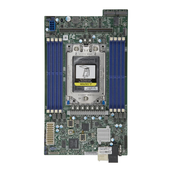
Introduction Congratulations on purchasing your computer motherboard from an industry leader. Supermicro motherboards are designed to provide you with the highest standards in quality and performance. In addition to the motherboard, several important parts that are included with the system are listed below. - Page 9 Chapter 1: Introduction Figure 1-1. BH12SSi-M25 Image Note: All graphics shown in this manual were based upon the latest PCB revision available at the time of publication of the manual. The motherboard you received may or may not look exactly the same as the graphics shown in this manual.
- Page 10 BH12SSi-M25 Motherboard User's Manual Figure 1-2. BH12SSi-M25 Layout...
-
Page 11: Quick Reference
Chapter 1: Introduction 1.1 Quick Reference 2X M.2 Connectors PCIe Gen 4 or SATA 2X PCIe GEN 4 Connectors PCIe x16 PCIe x16 JPWR1 JFP1 JBT1 DIMMA1 DIMMH1 DIMMB1 DIMMC1 DIMMG1 DIMMF1 DIMMD1 DIMME1 JCPLD1 MEZZ JTPM1 JDBG1 JPG1 JWD1 MB PWR JKVM1 PWR LED... -
Page 12: Quick Reference Table
BH12SSi-M25 Motherboard User's Manual Quick Reference Table Jumper Description Default Setting JDBG1 Debug Mode Pins 1-2 (Enabled) JBT1 Clear CMOS Open (Normal) JWD1 Watch Dog Timer control Pins 1-2 (Reset) JPG1 Onboard Video Disable/Enable Pins 1-2 (Enabled) Description Status PWR LED... -
Page 13: Motherboard Features
Chapter 1: Introduction Motherboard Features Features • Single AMD EPYC® 7002 series processor, in one SP3 socket Memory • Up to 2TB of ECC DDR4 3200 MHz speed, RDIMM/LRDIMM/3DS/NVDIMM memory in eight slots DIMM Size • Up to 128GB size at 1.2V Chipset •... - Page 14 BH12SSi-M25 Motherboard User's Manual Features Power Management • ACPI power management (S5) • Power button override mechanism • Power-on mode for AC power recovery System Health Monitoring • Onboard voltage monitoring for +1.8V, 3.3V, +5V, +12V, +3.3V Standby, +5V Standby, VBAT, HT, Memory •...
- Page 15 Chapter 1: Introduction BH12SSi-M25 AMD SP3 Rev. 1.00 SerDes Backplane Connector 25G x2 BIOS ROM 32MB G2 [18-15] CX4 25G LAN CPU USB2 [2] RTL8211FS TWO PORT AST2500 BMC ROM Mezzanine slot G3 [14] G1 [0-15] 32MB PCIE X16 AMD SP3 P0 [0-3] M.2 PCIE X4 / SATA...
-
Page 16: Processor And Chipset Overview
• System Management Bus (SMBus) Specification Version 2.0 1.3 Special Features This section describes the health monitoring features of the BH12SSi-M25. The motherboard has an onboard System Hardware Monitor chip that supports system health monitoring. Recovery from AC Power Loss The Basic I/O System (BIOS) provides a setting that determines how the system will respond when AC power is lost and then restored to the system. -
Page 17: Onboard Voltage Monitors
Chapter 1: Introduction Onboard Voltage Monitors The onboard voltage monitor will continuously scan crucial voltage levels. Once a voltage becomes unstable, it will give a warning or send an error message to the screen. Users can adjust the voltage thresholds to define the sensitivity of the voltage monitor. Real time readings of these voltage levels are all displayed in BMC. -
Page 18: Power Supply
BH12SSi-M25 Motherboard User's Manual 1.6 Power Supply As with all computer products, a stable power source is necessary for proper and reliable operation. It is even more important for processors that have high CPU clock rates. In areas where noisy power transmission is present, you may choose to install a line filter to shield the computer from noise. -
Page 19: Chapter 2 Installation
Chapter 2: Installation Chapter 2 Installation 2.1 Static-Sensitive Devices Electrostatic Discharge (ESD) can damage electronic com ponents. To prevent damage to your motherboard, it is important to handle it very carefully. The following measures are generally sufficient to protect your equipment from ESD. Precautions •... -
Page 20: Motherboard Installation
BH12SSi-M25 Motherboard User's Manual 2.2 Motherboard Installation All motherboards have standard mounting holes to fit different types of chassis. Make sure that the locations of all the mounting holes for both the motherboard and the chassis match. Although a chassis may have both plastic and metal mounting fasteners, metal ones are highly recommended because they ground the motherboard to the chassis. - Page 21 Chapter 2: Installation Figure 2-1. Motherboard Mounting Holes...
-
Page 22: Installing The Motherboard
BH12SSi-M25 Motherboard User's Manual Installing the Motherboard 1. Install the I/O shield into the back of the chassis (if applicable). 2. Locate the mounting holes on the motherboard. See the previous page for the locations. 3. Locate the matching mounting holes on the chassis. Align the mounting holes on the motherboard with the mounting holes on the chassis. -
Page 23: Processor And Heatsink Installation
CPU socket cap is in place and none of the socket pins are bent; otherwise, contact your retailer immediately. • Refer to the Supermicro website for updates on CPU support. Installing the Processor and Heatsink 1. Unscrew the screws holding down Force Frame in the sequence of 3-2-1. The screws are numbered on the force frame next to each screw hole. - Page 24 BH12SSi-M25 Motherboard User's Manual 2. The spring-loaded force frame will raise up after the last screw securing it (#1) is removed. Gently allow it to lift up to its stopping position. 3. Lift the rail frame up by gripping the lift tabs near the front end of the rail frame. While keeping a secure grip of the rail frame, lift it to a position so you can do the next step of removing the external cap.
- Page 25 Chapter 2: Installation 4. Remove the external cap from the Rail Frame by pulling it upwards through the rail guides on the rail frame. External Cap PnP Cover Cap 5. The CPU package is shipped from the factory with the blue carrier frame pre-assembled. Grip the handle of the carrier frame/CPU package assembly from its shipping tray, and while gripping the handle, align the flanges of the carrier frame onto the rails of the rail frame so its pins will be at the bottom when the rail frame is lowered later.
- Page 26 BH12SSi-M25 Motherboard User's Manual Note: You can only install the CPU inside the socket in one direction with the handle at the top. Make sure that it is properly inserted into the CPU socket before closing the rail frame plate. If it doesn't close properly, do not force it as it may damage your CPU. Instead, open the rail frame plate again, and double-check that the CPU is aligned properly.
- Page 27 Chapter 2: Installation 9. Gently lower the force frame down onto the rail frame and hold it in place until it is seated in the Socket housing. Note that the force frame is spring loaded and has to be held in place before it is secured. Important: Use a torque screwdriver, set it at 16.1 kgf-cm (14.0 lbf-in) with a Torx T20 screw head bit, to prevent damage to the CPU.
- Page 28 BH12SSi-M25 Motherboard User's Manual 11. After the force frame is secured and the CPU package is in place, now you must install the heatsink to the frame. Lower the heatsink down till it rests securely over the four screw holes on CPU package on the socket frame.
- Page 29 Chapter 2: Installation Uninstalling the Processor and Heatsink 1. Remove the heatsink attached to the top of the CPU package by reversing the installation procedure. 2. Clean the Thermal grease left by the heatsink on the CPU package lid to limit the risk of it contaminating the CPU package land pads or contacts in the socket housing.
-
Page 30: Memory Support And Installation
Important: Exercise extreme care when installing or removing DIMM modules to prevent any possible damage. Memory Support The BH12SSi-M25 supports up to 2TB of ECC DDR4 3200MHz speed, RDIMM/LRDIMM/3DS/ NVDIMM memory in eight slots. Refer to the table below for additional memory information. Populating RDIMM/RDIMM 3DS/LRDIMM/LRDIMM 3DS DDR4 Memory Modules... -
Page 31: Dimm Module Population
JPL1 IPMI_LAN Chapter 2: Installation JFPGA_SW1 JPG1:VGA 1-2:ENABLE JNCSI1 2-3:DISABLE DIMM Module Population JPB1:BMC 1-2:ENABLE When populating the motherboard with DIMM modules, please keep in mind the following: 2-3:DISABLE M.2-HC2 ACT LED13 USB4(3.0) • Always use DDR4 DIMM modules of the same type, size and speed. LED12 M.2-HC2 CPU PCI_E 4.0 X2... -
Page 32: Dimm Installation
BH12SSi-M25 Motherboard User's Manual DIMM Installation 1. Insert the desired number of DIMMs into the memory slots, there is no specific sequence or order required Receptive 2. Push the release tabs outwards on both Point ends of the DIMM slot to unlock it. -
Page 33: Connectors
Chapter 2: Installation 2.5 Connectors Main Connectors See the figure below for the locations and descriptions of the various I/O ports and connectors on the motherboard. A. 2x PCIe Gen 4 x16 connector for MCIO cable B. 2x M.2 Connector (PCIe Gen 4 x4 or 2 SATA support) C. - Page 34 BH12SSi-M25 Motherboard User's Manual 12V 8-pin Power Connector (JPWR1) JPWR1 is an 8-pin ATX power input to provide power to the motherboard. Refer to the table below for pin definitions. 12V 8-pin Power Connector Pin Definitions Pins Definition 1 through 4...
-
Page 35: Jumper Settings
Chapter 2: Installation 2.6 Jumper Settings How Jumpers Work To modify the operation of the motherboard, jumpers can be used to choose between optional settings. Jumpers create shorts between two pins to change the function of the connector. Pin #1 is identified with a thicker border line on the printed circuit board. See the diagram below for an example of jumping pins 1 and 2. - Page 36 BH12SSi-M25 Motherboard User's Manual Watch Dog (JWD1) JWD1 controls the Watch Dog function. Watch Dog is a monitor that can reboot the system when a software application hangs. Jumping pins 1-2 will cause Watch Dog to reset the system if an application hangs. Jumping pins 2-3 will generate a non-maskable interrupt signal for the application that hangs.
-
Page 37: Led Indicators
Chapter 2: Installation 2.7 LED Indicators Onboard Power LED (PWR LED) When the PWR LED is lit, it means the system is turned on, and all the system power rails are ready. When the system is turned off, or any one of the system power rails fails, this LED will turn off. -
Page 38: Chapter 3 Troubleshooting
BH12SSi-M25 Motherboard User's Manual Chapter 3 Troubleshooting 3.1 Troubleshooting Procedures Use the following procedures to troubleshoot your system. If you have followed all of the procedures below and still need assistance, refer to the ‘Technical Support Procedures’ and/ or ‘Returning Merchandise for Service’ section(s) in this chapter. Always disconnect the AC power cord before adding, changing or installing any non hot-swap hardware components. -
Page 39: No Video
Chapter 3: Troubleshooting No Video 1. If the power is on but you have no video, remove all the add-on cards and cables. 2. Check if memory module population is supported following guidelines on page 31, and re-seat memory DIMM module(s). Note: If you are a system integrator, VAR or OEM, a POST diagnostics card is recommended. -
Page 40: When The System Becomes Unstable
2. Memory support: Make sure that the memory modules are supported by testing the modules using memtest86 or a similar utility. Note: Refer to the product page on our website at http:\\www.supermicro.com for memory and CPU support and updates. 3. HDD support: Make sure that all hard disk drives (HDDs) work properly. Replace the bad HDDs with good ones. -
Page 41: Technical Support Procedures
Chapter 3: Troubleshooting 4. Identifying bad components by isolating them: If necessary, remove a component in question from the chassis, and test it in isolation to make sure that it works properly. Replace a bad component with a good one. 5. -
Page 42: Frequently Asked Questions
3.3 Frequently Asked Questions Question: What type of memory does my motherboard support? Answer: The BH12SSi-M25 motherboard supports up to two terabytes of ECC DDR4 2933/3200 MHz speed, RDIMM/LRDIMM/3DS/NVDIMM memory in eight slots. See Section 2.4 for details on installing memory. - Page 43 Chapter 3: Troubleshooting Question: When I run setup.exe to install AMD SP3 I/O drivers under windows, the Installshield wizard shows “Unable to save file: C:\AMD\AMD_Chipset_Drivers\..The system cannot find the path specified”. Answer: This happens under specific environments. Please click “ok”, and Installshield will prompt you to save the drivers to a folder you designate.
-
Page 44: Returning Merchandise For Service
BH12SSi-M25 Motherboard User's Manual 3.4 Returning Merchandise for Service A receipt or copy of your invoice marked with the date of purchase is required before any warranty service will be rendered. You can obtain service by calling your vendor for a Returned Merchandise Authorization (RMA) number. -
Page 45: Battery Removal
Chapter 3: Troubleshooting Battery Removal To remove the onboard battery, follow the steps below: 1. Power off your system and unplug your power cable. 2. Locate the onboard battery as shown below. 3. Using a tool such as a pen or a small screwdriver, push the battery lock outwards to unlock it. -
Page 46: Chapter 4 Uefi Bios
UEFI BIOS 4.1 Introduction This chapter describes the AMIBIOS™ Setup utility for the BH12SSi-M25 motherboard. The BIOS is stored on a chip and can be easily upgraded using a flash program. Note: Due to periodic changes to the BIOS, some settings may have been added or deleted and might not yet be recorded in this manual. -
Page 47: Main Setup
Note: The time is in the 24-hour format. For example, 5:30 P.M. appears as 17:30:00. The date's default value is 01/01/2015 after RTC reset. Supermicro BH12SSi BIOS Version This item displays the version of the BIOS ROM used in the system. - Page 48 BH12SSi-M25 Motherboard User's Manual Build Date This item displays the date when the version of the BIOS ROM used in the system was built. CPLD Version This item displays the CPLD version of the BIOS ROM used in the system.
-
Page 49: Advanced
Chapter 4: UEFI BIOS 4.3 Advanced Use the arrow keys to select a top item and press <Enter> to access the submenu items. Warning: Take caution when changing the Advanced settings. An incorrect value, a very high DRAM frequency, or an incorrect DRAM timing setting may make the system unstable. - Page 50 BH12SSi-M25 Motherboard User's Manual Bootup NumLock State Use this feature to set the Power on state for the <Numlock> key. The options are Off and On. Wait For "F1" If Error Use this feature to force the system to wait until the 'F1' key is pressed if an error occurs.
- Page 51 Chapter 4: UEFI BIOS Trusted Computing Security Device Support If this feature and the TPM jumper on the motherboard are both set to Enabled, onboard security devices will be enabled for TPM (Trusted Platform Module) support to enhance data integrity and network security.
- Page 52 BH12SSi-M25 Motherboard User's Manual ACPI Settings PCI AER Support The setting is used to enable or disable the ACPI OS to natively manage PCI Advanced Error Reporting. The options are Enabled and Disabled. High Precision Event Timer The High Precision Event Timer (HPET) can produce periodic interrupts and is used to synchronize multimedia streams, providing smooth playback and reducing the need to use other timestamp calculations.
- Page 53 Chapter 4: UEFI BIOS SOL Configuration Serial Port Select Enabled to enable the selected onboard serial port. The options are Disabled and Enabled. Change Settings This feature specifies the base I/O port address and the Interrupt Request address of a serial port specified by the user.
- Page 54 BH12SSi-M25 Motherboard User's Manual Parity A parity bit can be sent along with regular data bits to detect data transmission errors. Select Even if the parity bit is set to 0, and the number of 1's in data bits is even. Select Odd if the parity bit is set to 0, and the number of 1's in data bits is odd.
- Page 55 Chapter 4: UEFI BIOS Console Redirection Select Enabled to enable SOL console redirection support for a serial port specified by the user. The options are Enabled and Disabled. *If the item above set to Enabled, the following items will become available for user's configuration: Console Redirection Settings Terminal Type...
- Page 56 BH12SSi-M25 Motherboard User's Manual is full. Send a "Start" signal to start sending data when the receiving buffer is empty. The options are None and Hardware RTS/CTS. VT-UTF8 Combo Key Support Select Enabled to enable VT-UTF8 Combination Key support for ANSI/VT100 terminals.
- Page 57 Chapter 4: UEFI BIOS Console Redirection Settings Out-of-Band Mgmt Port The feature selects a serial port in a client server to be used by the Microsoft Windows Emergency Management Services (EMS) to communicate with a remote host server. The options are COM1, COM2 (Disabled), and AMT SOL.
- Page 58 BH12SSi-M25 Motherboard User's Manual Global C-state Control This setting is used to configure for Global C-state Control. Options include Auto, Disabled and Enabled. Local APIC Mode This setting is used to control the Local APIC (Advanced Programmable Interrupt Controller) Mode. Options include Auto, Disabled and Enabled.
- Page 59 Chapter 4: UEFI BIOS • L1 Data Cache (Size/Method) • L2 Data Cache (Size/Method) • L3 Cache per Socket (Size/Method) NB Configuration Determinism Control Use this setting to configure the Determinism Slider. Options include Auto, Power and Performance. cTDP Control Use this setting to configure the cTDP Control.
- Page 60 BH12SSi-M25 Motherboard User's Manual Preferred I/O This option enables the Preferred I/O for the bus number specified by Preferred I/O Bus. Options include Manual and Auto. Preferred I/O Bus This setting specifies the Preferred I/O Bus number. Default setting is 0.
- Page 61 Chapter 4: UEFI BIOS PCIe/PCI/PnP Configuration This menu provides PCIe/PCI/PnP configuration settings and information. PCI Bus Driver Version Above 4G Decoding This setting Enables or Disables 64-bit capable devices ability to be decoded in above 4G address space (only if the system supports 64-bit PCI decoding). SR-IOV Support If the system has SR-IOV capable PCIe devices, this setting will Enable or Disable the Single Root IO Virtualization Support for the system.
- Page 62 BH12SSi-M25 Motherboard User's Manual This setting enables or disables the listed PCIe Slot OPROM option. The options are Disabled, Legacy or EFI. Onboard LAN Use this setting to enable or disable the onboard LAN feature. The options are Enabled and Disabled.
- Page 63 Chapter 4: UEFI BIOS PXE Boot Wait Time This setting allows you to set in a number field the wait time to press the ESC key to abort the PXE boot. Default is 0. Media Detect Count This setting allows you set in a number field the number of times presence of media will be checked.
- Page 64 BH12SSi-M25 Motherboard User's Manual KMIP Server Configuration The Key Management Interoperability Protocol (KMIP) is an extensible communication protocol that defines message formats for the manipulation of cryptographic keys on a key management server. This facilitates data encryption by simplifying encryption key management.
- Page 65 Chapter 4: UEFI BIOS iSCSI Configuration iSCSI Initiator Name This feature allows the user to enter the unique name of the iSCSI Initiator in IQN format. Once the name of the iSCSI Initiator is entered into the system, configure the proper settings for the following items.
-
Page 66: Ipmi
BH12SSi-M25 Motherboard User's Manual 4.4 IPMI This tab allows you to configure the following IPMI settings for the system. Use this feature to configure Intelligent Platform Management Interface (IPMI) settings. BMC Firmware Revision This item indicates the IPMI firmware revision used in your system. - Page 67 Chapter 4: UEFI BIOS Erasing Settings Erase SEL Select Yes, On next reset to erase all system event logs upon next system reboot. Select Yes, On every reset to erase all system event logs upon each system reboot. Select No to keep all system event logs after each system reboot.
- Page 68 BH12SSi-M25 Motherboard User's Manual Station IP Address This item displays the Station IP address for this computer. This should be in decimal and in dotted quad form. Subnet Mask This item displays the sub-network that this computer belongs to. The value of each three- digit number separated by dots should not exceed 255.
-
Page 69: Event Logs
Chapter 4: UEFI BIOS 4.5 Event Logs This tab allows the user to configure the following event logs settings for the system. Change SMBIOS Event Log Settings This feature allows the user to configure SMBIOS Event settings. Enabling/Disabling Options SMBIOS Event Log Select Enabled to enable SMBIOS (System Management BIOS) Event Logging during system boot. - Page 70 BH12SSi-M25 Motherboard User's Manual When Log is Full Select Erase Immediately to immediately erase all errors in the SMBIOS event log when the event log is full. Select Do Nothing for the system to do nothing when the SMBIOS event log is full. The options are Do Nothing and Erase Immediately.
-
Page 71: Security
Chapter 4: UEFI BIOS 4.6 Security This tab allows you to configure the following security settings for the system. Administrator Password Press Enter to create a new, or change an existing Administrator password. Note that if the Administrator Password is erased, the User Password will be cleared as well. User Password Press Enter to create a new, or change an existing User password. - Page 72 BH12SSi-M25 Motherboard User's Manual Secure Boot This section contains options and menus for securing your boot mode and for key management. The following status message are displayed for the following: System Mode, Vendor Keys, Secure Boot Secure Boot This option allows you specify when the Platform Key (PK) is enrolled. When enabled, the System Mode is user deployed, and the CSM function is disabled.
- Page 73 Chapter 4: UEFI BIOS Device Guard Ready Remove 'UEFI CA' from DB This forces the Device Guard Ready system to not list the 'Microsoft UEFI CA' certificate in the Authorized Signature Database. The options are Yes and No. Restore DB Defaults Select Yes to to reset all database variables to factory defaults.
-
Page 74: Boot
BH12SSi-M25 Motherboard User's Manual 4.7 Boot Use this tab to configure Boot Settings: Boot Mode Select Use this item to select the type of device that the system is going to boot from. The options are LEGACY, UEFI, and DUAL. The default setting is DUAL. - Page 75 Chapter 4: UEFI BIOS UEFI Application Boot Priorities This feature allows the user to specify which UEFI devices are boot devices. • UEFI Boot Order #1 NETWORK Drive BBS Priorities This feature allows the user to specify which UEFI network drive devices are boot devices.
-
Page 76: Save & Exit
BH12SSi-M25 Motherboard User's Manual 4.8 Save & Exit Select the Save & Exit tab to enter the Save & Exit BIOS Setup screen. Discard Changes and Exit Select this option to quit the BIOS Setup without making any permanent changes to the system configuration, and reboot the computer. - Page 77 Chapter 4: UEFI BIOS Default Options Restore Defaults To set this feature, select Restore Defaults from the Save & Exit menu and press <Enter>. These are factory settings designed for maximum system stability, but not for maximum performance. Save as User Defaults To set this feature, select Save as User Defaults from the Exit menu and press <Enter>.
-
Page 78: Appendix A Software Installation
Appendix A Software Installation A.1 Installing Software Programs The Supermicro FTP site contains drivers and utilities for your system at ftp://ftp.supermicro. com. Some of these must be installed, such as the chipset driver. After accessing the FTP site, go into the CDR_Images directory and locate the ISO file for your motherboard. -
Page 79: Superdoctor 5
SATA settings back to your original settings. A.2 SuperDoctor ® The Supermicro SuperDoctor 5 is a hardware monitoring program that functions in a command-line or web-based interface in Windows and Linux operating systems. The program monitors system health information such as CPU temperature, system voltages, system power consumption, fan speed, and provides alerts via email or Simple Network Management Protocol (SNMP). -
Page 80: Appendix B Standardized Warning Statements
The following statements are industry standard warnings, provided to warn the user of situations which have the potential for bodily injury. Should you have questions or experience difficulty, contact Supermicro's Technical Support department for assistance. Only certified technicians should attempt to install or configure components. - Page 81 Appendix B: Standardized Warning Statements Attention Danger d'explosion si la pile n'est pas remplacée correctement. Ne la remplacer que par une pile de type semblable ou équivalent, recommandée par le fabricant. Jeter les piles usagées conformément aux instructions du fabricant. ¡Advertencia! Existe peligro de explosión si la batería se reemplaza de manera incorrecta.
-
Page 82: Product Disposal
BH12SSi-M25 Motherboard User's Manual B.2 Product Disposal Warning! Ultimate disposal of this product should be handled according to all national laws and regulations. 製品の廃棄 この製品を廃棄処分する場合、 国の関係する全ての法律 ・ 条例に従い処理する必要があります。 警告 本产品的废弃处理应根据所有国家的法律和规章进行。 警告 本產品的廢棄處理應根據所有國家的法律和規章進行。 Warnung Die Entsorgung dieses Produkts sollte gemäß allen Bestimmungen und Gesetzen des Landes erfolgen. -
Page 83: Appendix C Uefi Bios Recovery
Warning: Do not upgrade the BIOS unless your system has a BIOS-related issue. Flashing the wrong BIOS can cause irreparable damage to the system. In no event shall Supermicro be liable for direct, indirect, special, incidental, or consequential damages arising from a BIOS update. - Page 84 USB flash drive with FAT16 or FAT32 format and rename the file to SUPER.ROM. Note: If you cannot locate the "SUPER.ROM" file in your driver disk, visit our website at www.supermicro.com to download the correct BIOS image into a USB flash device and rename it "SUPER.ROM".
- Page 85 SUPERMICO BIOS Update: https://www.youtube.com/watch?v=S8z6iOEHGwY * If the BIOS flash recovery fails, contact our RMA Department to have the BIOS chip reprogrammed. This will require shipping the board to Supermicro for repair. Submit your RMA request at https://www.supermicro.com/support/rma Please make sure to follow all instructions when returning the motherboard.
Need help?
Do you have a question about the BH12SSi-M25 and is the answer not in the manual?
Questions and answers