Table of Contents
Advertisement
Quick Links
Advertisement
Table of Contents

Related Manuals for Supermicro B1SD2-TF


Summary of Contents for Supermicro B1SD2-TF
- Page 1 B1SD2-TF USER’S MANUAL Revision 1.0...
- Page 2 This product, including software and docu- mentation, is the property of Supermicro and/or its licensors, and is supplied only under a license. Any use or reproduction of this product is not allowed, except as expressly permitted by the terms of said license.
-
Page 3: About This Motherboard
Xeon ® D SoC (System-on- a-Chip) processor in a BGA package. The B1SD2-TF motherboard offers superior performance, power efficiency, and reliability while supporting cutting-edge technol- ogy such as Intel's Virtualization Technology, Turbo Boost Technology, QuickData Technology, and Hyper-Threading. This motherboard offers advanced I/O and controllers for networking and storage needs such as 10GbE and the ability to run 64-bit applications. -
Page 4: Conventions Used In The Manual
B1SD2-TF Motherboard User Manual Conventions Used in the Manual: Special attention should be given to the following symbols for proper installation and to prevent damage done to the components or injury to yourself: Warning: Critical information to prevent damage to the components or injury to your- self. -
Page 5: Contacting Supermicro
Super Micro Computer, Inc. 980 Rock Ave. San Jose, CA 95131 U.S.A. Tel: +1 (408) 503-8000 Fax: +1 (408) 503-8008 Email: marketing@supermicro.com (General Information) support@supermicro.com (Technical Support) Web Site: www.supermicro.com Europe Address: Super Micro Computer B.V. Het Sterrenbeeld 28, 5215 ML... -
Page 6: Table Of Contents
B1SD2-TF Motherboard User Manual Table of Contents Preface About This Motherboard ....................iii Manual Organization ..................... iii Conventions Used in the Manual: .................iv Contacting Supermicro ....................v Chapter 1 Introduction Overview ......................1-1 Checklist ......................1-1 Motherboard Features ..................1-6 Processor Overview ..................1-9 Special Features ................... - Page 7 Table of Contents VGA Enable ....................2-14 Watch Dog Timer Enable ................. 2-14 ME Recovery ................... 2-15 Manufacture Mode Select ................ 2-15 BIOS Recovery Enable ................2-16 BMC Enable .................... 2-16 Onboard Indicators ..................2-17 BMC Heartbeat LED ................2-17 SATA Connections ..................
- Page 8 B1SD2-TF Motherboard User Manual Appendix A BIOS Error Beep Codes BIOS Error Beep Codes .................A-1 Appendix B Software Installation Instructions Installing Software Programs ................B-1 Installing SuperDoctor5 ...................B-2 Appendix C UEFI BIOS Recovery Instructions An Overview to the UEFI BIOS ..............C-1 How to Recover the UEFI BIOS Image (the Main BIOS Block) .....C-1...
-
Page 9: Chapter 1 Introduction
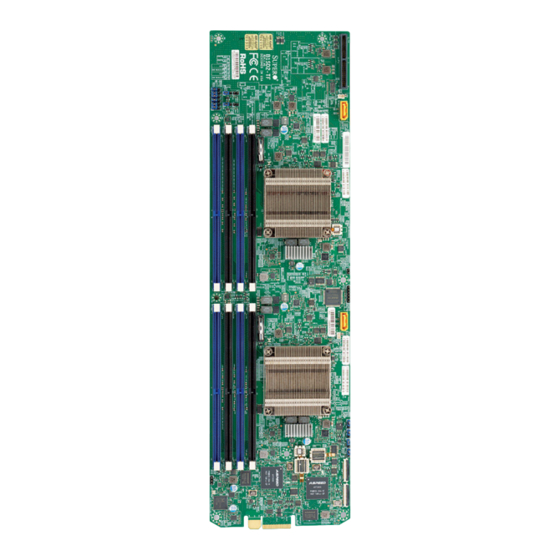
Checklist Congratulations on purchasing your computer motherboard from an acknowledged leader in the industry. Supermicro boards are designed with the utmost attention to detail to provide you with the highest standards in quality and performance. Please check that the following items have all been included with your motherboard. - Page 10 B1SD2-TF Motherboard User Manual B1SD2-TF Motherboard Image Note: All graphics shown in this manual were based upon the latest PCB Revision available at the time of publishing of the manual. The motherboard you've received may or may not look exactly the same as the graphics shown in this manual.
- Page 11 Chapter 1: Introduction B1SD2-TF Motherboard Layout P2-JWD1 P1-JBR1 P2-JBR1 P2-JSD1 P1-JPME2 P1-JPME1 P2-JPME2 P1-JWD1 P2-JPME1 P2-SATA4 P2-BT1 P2-JBT1 CPU2 P1-SATA4 P1-BT1 P1-JSD1 P1-JBT1 CPU1 P1-JPG1 P2-JPG1 P1-JPB1 P2-JPB1 LEDM2 LEDM1 Important Notes to the User 1. See Chapter 2 for detailed information on jumpers, I/O ports and JF1 front panel connections.
- Page 12 B1SD2-TF Motherboard User Manual B1SD2-TF Motherboard Quick Reference P2-JWD1 P1-JBR1 P2-JBR1 P2-JWD1 P1-JBR1 P2-JSD1 P2-JBR1 P2-JSD1 P1-JPME2 P1-JPME2 P1-JPME1 P2-JPME2 P1-JPME1 P1-JWD1 P2-SATA4 P2-JPME1 P2-SATA4 P1-JWD1 P2-JPME2 P2-JPME1 P2-BT1 P2-BT1 P2-JBT1 P2-JBT1 CPU2 P1-BT1 P1-SATA4 P1-SATA4 P1-BT1 P1-JSD1 P1-JSD1 P1-JBT1...
- Page 13 Chapter 1: Introduction Jumpers Jumper Description Default P1-JBR1 BIOS Recovery for Node 1 Pins 1-2 (Normal) P2-JBR1 BIOS Recovery for Node 2 Pins 1-2 (Normal) P1-JBT1 CMOS Clear for Node 1 Open (Normal) P2-JBT1 CMOS Clear for Node 2 Open (Normal) P1-JPG1 VGA Enable for Node 1 Pins 1-2 (Enabled)
-
Page 14: Motherboard Features
B1SD2-TF Motherboard User Manual Motherboard Features Intel ® Xeon ® D SoC (BGA Package) Each SoC supports 8 cores Memory Supports up to 128GB of DDR4 ECC VLP RDIMM memory of speeds up to 2400MHz in eight memory slots DIMM sizes... - Page 15 BMC Fan control and thermal alert by sensors monitor- ing, including CPU, memory and motherboard ambient temperatures System Management PECI (Platform Environment Configuration Interface) 3.0 IPMI View, Supermicro IPMI Tool, IPMI CFG System resource alert via SuperDoctor ® SuperDoctor ®...
- Page 16 B1SD2-TF Motherboard User Manual B1SD2-TF Motherboard Block Diagram CPU0 CPU1 Back Plane and Micro Blade System (Through Gold Finger) LAN1 LAN1 Switch 1 SATA GEN 3 SATA GEN 3 LAN2 Switch 2 LAN2 SATA Gen3 (Redundant) SATA Gen3 B1SA4-F-KVM B1SA4-F-KVM...
-
Page 17: Processor Overview
Chapter 1: Introduction Processor Overview The Intel ® Xeon ® D is the next generation, low-powered 64-bit SoC (System-on-a- Chip) processor in a BGA package. Built upon the functionality of the low-power 14nm architecture, the Xeon ® D processor provides superior performance and excellent power efficiency. -
Page 18: Special Features
B1SD2-TF Motherboard User Manual Special Features Recovery from AC Power Loss Basic I/O System (BIOS) provides a setting for you to determine how the system will respond when AC power is lost and then restored to the system. You can choose for the system to remain powered off, (in which case you must press the power switch to turn it back on), or for it to automatically return to a power-on state. -
Page 19: Acpi Features
Chapter 1: Introduction ACPI Features ACPI stands for Advanced Configuration and Power Interface. The ACPI specifica- tion defines a flexible and abstract hardware interface that provides a standard way to integrate power management features throughout a PC system, including its hardware, operating system and application software. This enables the system to automatically turn on and off peripherals such as CD-ROMs, network cards, hard disk drives and printers. - Page 20 B1SD2-TF Motherboard User Manual Notes 1-12...
-
Page 21: Chapter 2 Installation
The following statements are industry-standard warnings, provided to warn the user of situations which have the potential for bodily injury. Should you have questions or experience difficulty, contact Supermicro's Technical Support department for assis- tance. Only certified technicians should attempt to install or configure components. - Page 22 B1SD2-TF Motherboard User Manual Attention Danger d'explosion si la pile n'est pas remplacée correctement. Ne la remplacer que par une pile de type semblable ou équivalent, recommandée par le fabricant. Jeter les piles usagées conformément aux instructions du fabricant. ¡Advertencia! Existe peligro de explosión si la batería se reemplaza de manera incorrecta.
-
Page 23: Product Disposal
Chapter 2: Installation Product Disposal Warning! Ultimate disposal of this product should be handled according to all national laws and regulations. 製品の廃棄 この製品を廃棄処分する場合、 国の関係する全ての法律 ・ 条例に従い処理する必要が あり ます。 警告 本产品的废弃处理应根据所有国家的法律和规章进行。 警告 本產品的廢棄處理應根據所有國家的法律和規章進行。 Warnung Die Entsorgung dieses Produkts sollte gemäß allen Bestimmungen und Gesetzen des Landes erfolgen. -
Page 24: Static-Sensitive Devices
B1SD2-TF Motherboard User Manual القىانين واللىائح الىطنية جميع وفقا ل ينبغي التعامل معه هذا المنتج من التخلص النهائي عند 경고! 이 제품은 해당 국가의 관련 법규 및 규정에 따라 폐기되어야 합니다. Waarschuwing De uiteindelijke verwijdering van dit product dient te geschieden in overeenstemming met alle nationale wetten en reglementen. -
Page 25: Motherboard Installation
Chapter 2: Installation Motherboard Installation All motherboards have standard mounting holes to fit different types of chassis. Make sure that the locations of all the mounting holes for both motherboard and chassis match. Although a chassis may have both plastic and metal mounting fas- teners, metal ones are highly recommended because they ground the motherboard to the chassis. - Page 26 B1SD2-TF Motherboard User Manual The B1SD2-TF motherboard fits into a mounting tray that also holds the hard drives. See the image below: Mounting Tray B1SD2-TF Motherboard Hard Disk Drives Microblade Chassis Mounting tray with B1SD2-TF moth- erboard slides into the Microblade chassis.
-
Page 27: Installing The Motherboard
Chapter 2: Installation Installing the Motherboard 1. Locate the mounting holes on the motherboard and mounting tray. Align the mounting holes on the motherboard against the mounting holes on the mounting tray. 2. Install standoffs on the mounting tray as needed. 3. -
Page 28: Ddr4 Memory Support
B1SD2-TF Motherboard User Manual DDR4 Memory Support The B1SD2-TF supports up to 128 GB of DDR4 ECC VLP (Very Low Profile) RDIMM memory of speeds up to 2400MHz in eight (8) slots. Populating these DIMM modules with a pair of memory modules of the same type and size will result in interleaved memory, which will improve memory performance. -
Page 29: Dimm Installation
Chapter 2: Installation DIMM Installation 1. Insert the desired number of DIMMs P2-JWD1 P1-JBR1 P2-JBR1 P2-JSD1 P1-JPME2 into the memory slots in the following P1-JPME1 P2-JPME2 P1-JWD1 P2-JPME1 P2-SATA4 order: P1-DIMMA1, P1-DIMMB1, P2-BT1 P2-JBT1 P1-DIMMA2, P1-DIMMB2, then P2- DIMMA1, P2-DIMMB1, P2-DIMMA2, CPU2 P2-DIMMB2. -
Page 30: Memory Population Guidelines
B1SD2-TF Motherboard User Manual Memory Population Guidelines Please follow the table below when populating the B1SD2-TF. Recommended Population for P1 DIMM Slots P1-DIMMA1 P1- DIMMB1 P1- DIMMA2 P1- DIMMB2 Total System Memory 16GB 16GB 32GB 16GB 16GB 32GB 16GB 16GB... -
Page 31: Connectors
Chapter 2: Installation Connectors DOM Power Connectors DOM PWR Pin Definitions The Disk-On-Module (DOM) power Pin# Definition connectors, located at P1-JSD1 and P2-JSD1, provide 5V power to a solid Ground state DOM storage device connected Ground to one of the SATA ports. See the table on the right for pin definitions. -
Page 32: Jumper Settings
B1SD2-TF Motherboard User Manual Jumper Settings Explanation of Jumpers To modify the operation of the motherboard, jumpers can be used to choose between optional settings. Jumpers create shorts between two pins to change the function of the connector. Pin 1 is identified with a square solder pad on the printed circuit board. -
Page 33: Cmos Clear
Chapter 2: Installation CMOS Clear P1- JBT1 (for Node 1) and P2-JBT1 (for Node 2) are used to clear the CMOS. Instead of pins, this "jumper" consists of contact pads to prevent accidental clear- ing of CMOS. To clear CMOS, use a metal object such as a small screwdriver to touch both pads at the same time to short the connection. -
Page 34: Vga Enable
B1SD2-TF Motherboard User Manual VGA Enable VGA Enable P1-JPG1 allows the user to enable the on- Jumper Settings board VGA connector for Node 1, and P2- Pin # Definition JPG1 enables the onboard VGA connector Enabled (Default) for Node 2. The default setting is pins 1-2 to Disabled enable the connection. -
Page 35: Me Recovery
Chapter 2: Installation ME Recovery ME Recovery Jumper Settings Set P1-JPME1 (for Node 1) and P2- Pin # Definition JPME1 (for Node 2) to select ME Firm- Normal (Default) ware Recovery mode, which will limit ME Recovery system resource for essential function use only without putting restrictions on power use. -
Page 36: Bios Recovery Enable
B1SD2-TF Motherboard User Manual BIOS Recovery Enable BIOS Recovery Jumper Settings Close pins 2 and 3 of jumpers P1-JBR1 Pin # Definition (for Node 1) and P2-JBR1 (for Node 2) Normal for BIOS recovery. The default setting is BIOS Recovery on pins 1 and 2 for normal operation. -
Page 37: Onboard Indicators
Chapter 2: Installation Onboard Indicators BMC Heartbeat LED BMC Heartbeat LED Status A BMC Heartbeat LED for Node 1 is lo- Color/State Definition cated at LEDM1, and an LED for Node 2 Green:Blinking BMC: Normal is located at LEDM2. See the table on the right for more information. -
Page 38: Sata Connections
B1SD2-TF Motherboard User Manual SATA Connections Serial ATA Ports There are two SATA 3.0 connections (P1-SATA4 and P2-SATA4) available on the motherboard. These ports provide serial-link signal connections, which are faster than the connections of Parallel ATA. See the table on the right for pin definitions. -
Page 39: Troubleshooting Procedures
Chapter 3: Troubleshooting Chapter 3 Troubleshooting Troubleshooting Procedures Use the following procedures to troubleshoot your system. If you have followed all of the procedures below and still need assistance, refer to the ‘Technical Support Procedures’ and/or ‘Returning Merchandise for Service’ section(s) in this chapter. Always disconnect the AC power cord before adding, changing or installing any hardware components. -
Page 40: Memory Errors
B1SD2-TF Motherboard User Manual 2. Use the speaker to determine if any beep codes exist. (Refer to Appendix A for details on beep codes.) 3. Remove all memory modules and turn on the system. (If the alarm is on, check the specifications of memory modules, reset the memory or try a different one.) -
Page 41: Technical Support Procedures
Before contacting Technical Support, please make sure that you have followed all the steps listed below. Also, Note that as a motherboard manufacturer, Supermicro does not sell directly to end users, so it is best to first check with your distributor or reseller for troubleshooting services. -
Page 42: Frequently Asked Questions
Frequently Asked Questions Question: What type of memory does my motherboard support? Answer: The B1SD2-TF motherboard supports up to 128GB of DDR4 ECC VLP RDIMM memory of speeds up to 2400MHz. See Section 2-4 for details on install- ing memory. -
Page 43: Battery Removal And Installation
Chapter 3: Troubleshooting Battery Removal and Installation Battery Removal To remove the onboard battery, follow the steps below: 1. Power off your system and unplug your power cable. 2. Locate the onboard battery as shown below. 3. Using a tool such as a pen or a small screwdriver, push the battery lock out- wards to unlock it. -
Page 44: Returning Merchandise For Service
You can obtain service by calling your vendor for a Returned Merchandise Authorization (RMA) number. For faster service, you may also obtain RMA authorizations online (http://www.supermicro. com/RmaForm/). When you return the motherboard to the manufacturer, the RMA number should be prominently displayed on the outside of the shipping carton, and mailed prepaid or hand-carried. -
Page 45: Introduction
When an option is selected in the left frame, it is highlighted in white. Often a text message will accompany it. (Note: the AMI BIOS has default text messages built in. Supermicro retains the option to include, omit, or change any of these text messages.) The AMI BIOS setup utility uses a key-based navigation system called "hot keys". -
Page 46: How To Start The Setup Utility
Flashing the wrong BIOS can cause irreparable damage to the system. In no event shall Supermicro be liable for direct, indirect, special, incidental, or consequential dam- ages arising from a BIOS update. If you have to update the BIOS, do not shut down or reset the system while the BIOS is updating. - Page 47 Day MM/DD/YY format. The time is entered in HH:MM:SS format. Note: The time is in the 24-hour format. For example, 5:30 P.M. appears as 17:30:00. The following BIOS items will also be displayed: Supermicro B1SD2-TF Version Build Date Memory Information Total Memory This displays the total size of memory available in the system.
-
Page 48: Advanced
B1SD2-TF Motherboard User’s Manual Advanced Use the arrow keys to select Boot Setup and press <Enter> to access the submenu items. Warning: Take caution when changing the Advanced settings. An incorrect value, a very high DRAM frequency, or an incorrect DRAM timing setting may make the system unstable. - Page 49 Chapter 4: AMI BIOS Wait For 'F1' If Error Use this feature to force the system to wait until the 'F1' key is pressed if an error occurs. The options are Disabled and Enabled. INT19 (Interrupt 19) Trap Response Interrupt 19 is the software interrupt that handles the boot disk function. When this item is set to Immediate, the ROM BIOS of the host adaptors will "capture"...
- Page 50 B1SD2-TF Motherboard User’s Manual CPU Configuration The following CPU information will be displayed: • Processor ID • Processor Frequency • Processor Max Ratio • Processor Min Ratio • Microcode Revision • L1 Cache RAM • L2 Cache RAM •...
- Page 51 Chapter 4: AMI BIOS Execute Disable Bit (Available if supported by the OS & the CPU) Select Enabled to enable the Execute-Disable Bit which will allow the processor to designate areas in the system memory where an application code can execute and where it cannot, thus preventing a worm or a virus from flooding illegal codes to overwhelm the processor or damage the system during an attack.
- Page 52 B1SD2-TF Motherboard User’s Manual Intel ® Virtualization Technology (Available when supported by the CPU) Select Enabled to support Intel ® Virtualization Technology, which will allow one platform to run multiple operating systems and applications in independent parti- tions, creating multiple "virtual" systems in one physical computer. The options are Enable and Disable.
- Page 53 Chapter 4: AMI BIOS Boot Performance Mode This feature allows the user to select the performance state that the BIOS will set before the operating system handoff. The options are Max Performance and Max Efficient. Turbo Mode Select Enable for processor cores to run faster than the frequency specified by the manufacturer.
- Page 54 B1SD2-TF Motherboard User’s Manual Enhanced Halt State (C1E) Select Enabled to use Enhanced Halt-State technology, which will significantly reduce the CPU's power consumption by reducing the CPU's clock cycle and voltage during a Halt-state. The options are Disable and Enable.
- Page 55 Chapter 4: AMI BIOS SAPM Control This feature indicates whether the PCU should control the System Agent PM using its power-performance tuning algorithm. The options are Disable and Enable. Energy Efficient Turbo Use this feature to enable energy efficient turbo mode. The options are Dis- able and Enable.
- Page 56 B1SD2-TF Motherboard User’s Manual No Snoop Select Enable to support no-snoop mode for each CB device. The options are Disable and Enable. ® VT for Directed I/O (VT-d) Intel Intel ® VT for Directed I/O (VT-d) Select Enable to use Intel ® Virtualization Technology support for Direct I/O VT-d support by reporting the I/O device assignments to the VMM (Virtual Machine Monitor) through the DMAR ACPI Tables.
- Page 57 Chapter 4: AMI BIOS Set Throttling Mode Throttling improves reliability and reduces power consumption in the processor via automatic voltage control during processor idle states. The options are Dis- abled and CLTT (Closed Loop Thermal Throttling). A7 Mode Select Enabled to support the A7 (Addressing) mode to improve memory perfor- mance.
- Page 58 B1SD2-TF Motherboard User’s Manual Demand Scrub Demand Scrubbing is a process that allows the CPU to correct correctable memory errors found on a memory module. When the CPU or I/O issues a demand-read command, and the read data from memory turns out to be a correctable error, the error is corrected and sent to the requestor (the original source).
- Page 59 Chapter 4: AMI BIOS EHCI1 Select Enabled to enable EHCI (Enhanced Host Controller Interface) support on USB 2.0 connector #1 (at least one USB 2.0 connector should be enabled for EHCI support). The options are Disabled and Enabled. EHCI2 Select Enabled to enable EHCI (Enhanced Host Controller Interface) support on USB 2.0 connector #2 (at least one USB 2.0 connector should be enabled for EHCI support).
- Page 60 B1SD2-TF Motherboard User’s Manual SATA Port 0 ~ Port 4 This item displays the information detected on the installed SATA drive on the particular SATA port. • Model number of drive and capacity • Software Preserve Support Port 0 ~ Port 4 Hot Plug This feature designates this port for hot plugging.
- Page 61 Chapter 4: AMI BIOS • ME Firmware Status #1 • ME Firmware Status #2 • Current State • Error Code PCIe/PCI/PnP Configuration The following information will display: • PCI Bus Driver Version • PCI Devices Common Settings: PCI PERR/SERR Support Select Enabled to allow a PCI device to generate a PERR/SERR number for a PCI Bus Signal Error Event.
- Page 62 B1SD2-TF Motherboard User’s Manual Onboard LAN Option ROM Type Select Enabled to enable Option ROM support to boot the computer using a network device specified by the user. The options are Disabled, Legacy and EFI. P1 Onboard LAN1 Option ROM Use this option to select the type of device installed in LAN Port 1 used for system boot.
- Page 63 Chapter 4: AMI BIOS Change Port 1 Settings This feature specifies the base I/O port address and the Interrupt Request address of a serial port specified by the user. Select Auto to allow the BIOS to automatically assign the base I/O and IRQ address. The options for Serial Port 1 are Auto, (IO=3F8h;...
- Page 64 B1SD2-TF Motherboard User’s Manual Parity A parity bit can be sent along with regular data bits to detect data transmission errors. Select Even if the parity bit is set to 0, and the number of 1's in data bits is even. Select Odd if the parity bit is set to 0, and the number of 1's in data bits is odd.
- Page 65 Chapter 4: AMI BIOS Redirection After BIOS Post Use this feature to enable or disable legacy console redirection after BIOS POST. When set to Bootloader, legacy console redirection is disabled before booting the OS. When set to Always Enable, legacy console redirection remains enabled when booting the OS.
- Page 66 B1SD2-TF Motherboard User’s Manual Stop Bits A stop bit indicates the end of a serial data packet. Select 1 Stop Bit for standard serial data communication. Select 2 Stop Bits if slower devices are used. The op- tions are 1 and 2.
- Page 67 Chapter 4: AMI BIOS EMS (Emergency Management Services) Console Redirection Select Enabled to use a COM port selected by the user for EMS Console Redirec- tion. The options are Enabled and Disabled. *If the item above set to Enabled, the following items will become available for user's configuration: EMS Console Redirection Settings This feature allows the user to specify how the host computer will exchange data...
- Page 68 B1SD2-TF Motherboard User’s Manual ACPI Settings WHEA Support This feature Enables the Windows Hardware Error Architecture (WHEA) support for the Windows 2008 (or a later version) operating system. The options are Enabled and Disabled. High Precision Event Timer Select Enabled to activate the High Performance Event Timer (HPET) that produces...
-
Page 69: Event Logs
Chapter 4: AMI BIOS Event Logs Use this feature to configure Event Log settings. Change SMBIOS Event Log Settings Enabling/Disabling Options SMBIOS Event Log Change this item to enable or disable all features of the SMBIOS Event Logging during system boot. The options are Enabled and Disabled. Runtime Error Logging Support Select Enabled to support Runtime Error Logging. - Page 70 B1SD2-TF Motherboard User’s Manual PCI-Ex (PCI-Express) Error Enable Select Yes for the BIOS to correct errors occurred in the PCI-E slots. The options are Yes and No. Erasing Settings Erase Event Log If No is selected, data stored in the event log will not be erased. Select Yes, Next Reset, data in the event log will be erased upon next system reboot.
-
Page 71: Ipmi
Chapter 4: AMI BIOS IPMI Use this feature to configure Intelligent Platform Management Interface (IPMI) settings. BMC Firmware Revision This item indicates the IPMI firmware revision used in your system. IPMI Status (Baseboard Management Controller) This item indicates the status of the IPMI firmware installed in your system. System Event Log ... - Page 72 B1SD2-TF Motherboard User’s Manual When SEL is Full This feature allows the user to decide what the BIOS should do when the system event log is full. Select Erase Immediately to erase all events in the log when the system event log is full. The options are Do Nothing and Erase Immediately.
- Page 73 Chapter 4: AMI BIOS Station MAC Address This item displays the Station MAC address for this computer. Mac addresses are 6 two-digit hexadecimal numbers. Gateway IP Address This item displays the Gateway IP address for this computer. This should be in decimal and in dotted quad form (i.e., 172.31.0.1).
-
Page 74: Security Settings
B1SD2-TF Motherboard User’s Manual Security Settings This menu allows the user to configure the following security settings for the system. Password Check Select Setup for the system to check for a password at Setup. Select Always for the system to check for a password at bootup or upon entering the BIOS Setup utility. - Page 75 Chapter 4: AMI BIOS Secure Boot Use this item to enable secure boot. The options are Disabled and Enabled. Secure Boot Mode Use this item to select the secure boot mode. The options are Standard and Custom. Key Management This submenu allows the user to configure the following Key Management settings.
- Page 76 B1SD2-TF Motherboard User’s Manual Authorized Signatures Set New Key Select Yes to load the database from the manufacturer's defaults. Select No to load the DB from a file. The options are Yes and No. Append Key Select Yes to add the database from the manufacturer's defaults to the existing DB.
-
Page 77: Boot
Chapter 4: AMI BIOS Boot Use this feature to configure Boot Settings: Setup Prompt Timeout Use this item to indicate the length of time (the number of seconds) for the BIOS to wait before rebooting the system when the setup activation key is pressed. Enter the value of 65535 (0xFFFF) for the BIOS to wait indefinitely. - Page 78 B1SD2-TF Motherboard User’s Manual • Dual Boot Option #6 • Dual Boot Option #7 • Dual Boot Option #8 • Dual Boot Option #9 • Dual Boot Option #10 • Dual Boot Option #11 • Dual Boot Option #12 •...
-
Page 79: Save & Exit
Chapter 4: AMI BIOS Save & Exit Select the Exit tab from the BIOS setup utility screen to enter the Exit BIOS Setup screen. Discard Changes and Exit Select this option to quit the BIOS Setup without making any permanent changes to the system configuration, and reboot the computer. - Page 80 B1SD2-TF Motherboard User’s Manual Restore Defaults To set this feature, select Restore Defaults from the Save & Exit menu and press <Enter>. These are factory settings designed for maximum system stability, but not for maximum performance. Save As User Defaults To set this feature, select Save as User Defaults from the Exit menu and press <En-...
-
Page 81: Appendix A Bios Error Beep Codes
Appendix A: POST Error Beep Codes Appendix A BIOS Error Beep Codes During the POST (Power-On Self-Test) routines, which are performed each time the system is powered on, errors may occur. Non-fatal errors are those which, in most cases, allow the system to continue with bootup. - Page 82 B1SD2-TF Motherboard User Manual Notes...
-
Page 83: Appendix B Software Installation Instructions
Appendix B Software Installation Instructions B-1 Installing Software Programs The Supermicro ftp site contains drivers and utilities for your system at ftp://ftp. supermicro.com. Some of these must be installed, such as the chipset driver. After accessing the ftp site, go into the CDR_Images directory and locate the ISO file for your motherboard. -
Page 84: B-2 Installing Superdoctor5
SATA settings back to your original settings. B-2 Installing SuperDoctor5 The Supermicro SuperDoctor® 5 is a hardware monitoring program that functions in a command-line or web-based interface in Windows and Linux operating systems. The program monitors system health information such as CPU temperature, system voltages, system power consumption, fan speed, and provides alerts via email or Simple Network Management Protocol (SNMP). - Page 85 Appendix B: Software Installation Instructions SuperDoctor 5 Interface Display Screen (Health Information) Note: The SuperDoctor 5 program and User’s Manual can be downloaded from the Supermicro web site at http://www.supermicro.com/products/nfo/ sms_sd5.cfm.
- Page 86 B1SD2-TF Motherboard User Manual Notes...
-
Page 87: Appendix C Uefi Bios Recovery Instructions
Flashing the wrong BIOS can cause irreparable damage to the system. In no event shall Supermicro be liable for direct, indirect, special, incidental, or consequential damages arising from a BIOS update. If you need to update the BIOS, do not shut down or reset the system while the BIOS is updating to avoid possible boot failure. - Page 88 Root "\" Directory of a USB device or a writeable CD/DVD. Note: If you cannot locate the "Super.ROM" file in your driver disk, visit our website at www.supermicro.com to download the BIOS image into a USB flash device and rename it "Super ROM" for BIOS recovery use.
- Page 89 Appendix C: UEFI BIOS Recovery 6. After the process of BIOS Recovery is complete, press any key to reboot the system. 7. Using a different system, extract the BIOS package into a bootable USB flash drive. 8. When a DOS prompt appears, enter AMI.BAT BIOSname.### at the prompt. Note: Do not interrupt this process until BIOS flashing is completed.
- Page 90 B1SD2-TF Motherboard User Manual 9. After seeing the message that BIOS update is completed, unplug the AC pow- er cable from the power supply to clear CMOS, and then plug the AC power cable in the power supply again to power on the system.
-
Page 91: Appendix D Dual Boot Block
Appendix D: Dual Boot Block Appendix D Dual Boot Block D-1 Introduction This motherboard supports the Dual Boot Block feature, which is the last-ditch mechanism to recover the BIOS boot block. This section provides an introduction to the feature. BIOS Boot Block A BIOS boot block is the minimum BIOS loader required to enable necessary hardware components for the BIOS crisis recovery flash that will update the main BIOS block. -
Page 92: D-2 Steps For Using Jumpers P1-Jbr1 And P2-Jbr1
B1SD2-TF Motherboard User Manual D-2 Steps for Using Jumpers P1-JBR1 and P2-JBR1 1. Power down the system. 2. Close pins 2-3 on Jumpers P1-JBR1 and P1-JBR1 and power on the system. 3. Follow the BIOS recovery SOP listed in the previous chapter (Appendix C). - Page 93 (Disclaimer Continued) The products sold by Supermicro are not intended for and will not be used in life support systems, medical equipment, nuclear facilities or systems, aircraft, aircraft devices, aircraft/emergency com- munication devices or other critical systems whose failure to perform be reasonably expected to result in significant injury or loss of life or catastrophic property damage.
Need help?
Do you have a question about the B1SD2-TF and is the answer not in the manual?
Questions and answers