Sign In
Upload
Manuals
Brands
SMC Networks Manuals
Controller
LECSN-T Series
SMC Networks LECSN-T Series Manuals
Manuals and User Guides for SMC Networks LECSN-T Series. We have
2
SMC Networks LECSN-T Series manuals available for free PDF download: Operation Manual
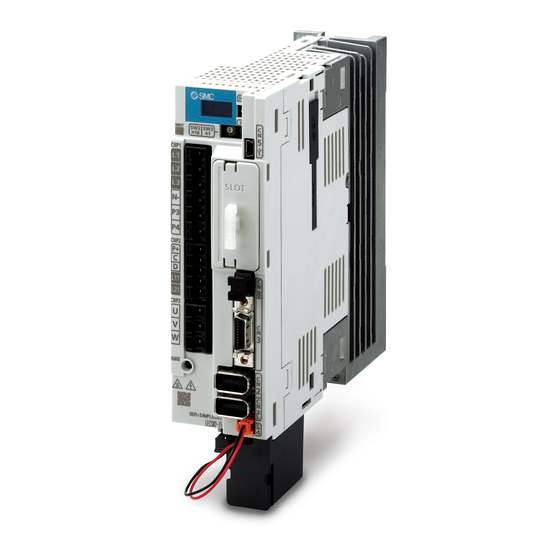
SMC Networks LECSN-T Series Operation Manual (1046 pages)
AC Servo Motor Driver (Network card type)
Brand:
SMC Networks
| Category:
Controller
| Size: 12 MB
Table of Contents
2. Installation
45
Table of Contents
45
Installation
46
Installation Direction and Clearances
47
Keep out Foreign Materials
49
Encoder Cable Stress
49
Inspection Items
49
Parts Having Service Lives
50
Restrictions When Using this Product at Altitude Exceeding 1000 M and up to 2000 M above Sea Level
51
3. Signals and Wiring
52
Signals and Wiring
53
Input Power Supply Circuit
54
I/O Signal Connection Example
58
For Sink I/O Interface
58
For Source I/O Interface
59
Explanation of Power Supply System
60
Signal Explanations
60
Power-On Sequence
61
Wiring CNP1, CNP2, and CNP3
62
Connectors and Pin Assignment
64
Signal (Device) Explanations
66
Input Device
66
Output Device
68
Output Signal
70
Power Supply
70
Forced Stop Deceleration Function
71
Base Circuit Shut-Off Delay Time Function
73
Vertical Axis Freefall Prevention Function
74
Residual Risks of the Forced Stop Function (EM2)
74
Alarm Occurrence Timing Chart
75
When You Use the Forced Stop Deceleration Function
75
When You Do Not Use the Forced Stop Deceleration Function
76
Interfaces
77
Internal Connection Diagram
77
Detailed Explanation of Interfaces
78
Source I/O Interfaces
80
Servo Motor with a Lock
81
Safety Precautions
81
Timing Chart
82
Wiring Diagrams (LE-□-□ Series Servo Motor)
88
Grounding
89
4. Startup
90
Startup
91
Switching Power on for the First Time
92
Startup Procedure
92
Wiring Check
93
Surrounding Environment
94
Startup
94
Switch Setting and Display of the Driver
96
Switches
96
Scrolling Display
97
Status Display of an Axis
99
Test Operation
101
Test Operation Mode
101
Test Operation Mode in Setup Software (MR Configurator2 TM )
102
Motor-Less Operation in Upper Side
106
Table of Contents
107
Parameter List
108
Basic Setting Parameters ([Pr. PA
123
Gain/Filter Setting Parameters ([Pr. PB
137
Extension Setting Parameters ([Pr. PC
150
I/O Setting Parameters ([Pr. PD
170
I/O Extension Setting 2 Parameters ([Pr. PE
174
Extension Setting 3 Parameters ([Pr. PF
178
Positioning Control Parameters ([Pr. PT
180
6. Normal Gain Adjustment
209
Different Adjustment Methods
210
Adjustment on a Single Driver
210
Adjustment Using Setup Software (MR Configurator2 TM )
211
One-Touch Tuning
212
One-Touch Tuning Flowchart
213
Display Transition and Operation Procedure of One-Touch Tuning
214
Caution for One-Touch Tuning
219
Auto Tuning
220
Auto Tuning Mode
220
Auto Tuning Mode Basis
221
Adjustment Procedure by Auto Tuning
222
Response Level Setting in Auto Tuning Mode
223
Manual Mode
224
2Gain Adjustment Mode
228
7. Special Adjustment Functions
230
Filter Setting
231
Machine Resonance Suppression Filter
231
Adaptive Filter II
234
Shaft Resonance Suppression Filter
236
Low-Pass Filter
237
Advanced Vibration Suppression Control II
237
Command Notch Filter
242
Gain Switching Function
243
Applications
243
Function Block Diagram
244
Parameter
245
Gain Switching Procedure
248
Tough Drive Function
252
Vibration Tough Drive Function
252
Instantaneous Power Failure Tough Drive Function
254
Compliance with SEMI-F47 Standard
258
Model Adaptive Control Disabled
260
Lost Motion Compensation Function
261
Super Trace Control
264
Table of Contents
266
Explanations of the Lists
267
Alarm List
268
Warning List
276
Remedies for Alarms
279
Remedies for Warnings
319
Troubleshooting at Power on
330
Trouble Which Does Not Trigger an Alarm/Warning
331
10. Characteristics
337
Overload Protection Characteristics
338
10.2 Power Supply Capacity and Generated Loss
341
Dynamic Lock Characteristics
341
Dynamic Lock Operation
341
Permissible Load to Motor Inertia When the Dynamic Lock Is Used
342
Cable Bending Life
343
Inrush Currents at Power-On of Main Circuit and Control Circuit
344
11. Options and Peripheral Equipment
345
Cable/Connector Sets
346
Combinations of Cable/Connector Sets
347
STO Cable
350
Encoder Cable/Connector Sets
351
Motor Cables
353
Lock Cables
354
Regenerative Options
355
Combination and Regenerative Power
355
Parameter Setting
355
Selection of Regenerative Option
356
Dimensions
357
Setup Software (MR Configurator2 TM )
358
Specifications
358
System Configuration
359
Precautions for Using USB Communication Function
360
Battery (LEC-MR-BAT6V1SET-A)
361
Molded-Case Circuit Breakers, Fuses, Magnetic Contactors (Recommended)
364
Relay (Recommended)
364
Selection Example of Wires
364
Noise Reduction Techniques
365
Earth-Leakage Current Breaker
373
EMC Filter (Recommended)
375
12. Absolute Position Detection System
379
12.1 Summary
380
Features
380
Parameter Setting
380
Structure
380
Confirmation of Absolute Position Detection Data
381
Battery
382
Battery Replacement Procedure
383
13. Using Sto Function
385
Introduction
386
Terms Related to Safety
386
Cautions
386
Residual Risks of the STO Function
387
Specifications
388
Maintenance
389
STO I/O Signal Connector (CN8) and Signal Layouts
389
Signal Layouts
389
Signal (Device) Explanations
390
How to Pull out the STO Cable
390
Connection Example
391
Connection Example for CN8 Connector
391
External I/O Signal Connection Example Using an MR-J3-D05 Safety Logic Unit of Mitsubishi Electric Corporation
392
External I/O Signal Connection Example Using an External Safety Relay Unit
394
Detailed Description of Interfaces
395
Sink I/O Interface
395
Source I/O Interface
397
15. Servo Motor
400
Servo Motor
401
Servo Motor with a Lock
401
Features
401
Characteristics of Servo Motor with a Lock
403
Cable
404
Protection from Oil and Water
404
Rated Speed of Servo Motor
404
Mounting Connectors
405
16. How to Use the Point Table
406
How to Use the Point Table
408
Specification List
408
Switching Power on for the First Time
409
Switching Power on for the First Time Point Table Mode (Pt)
411
Point Table Mode (Pt)
411
Automatic Operation Using Point Table
411
Jog Mode (Jg)
429
Point Table Setting Method
431
Point Table Setting Method with Setup Software
431
Point Table Setting Method with Objects
434
Advertisement
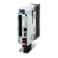
SMC Networks LECSN-T Series Operation Manual (48 pages)
AC Servo Motor Driver
Brand:
SMC Networks
| Category:
Controller
| Size: 3 MB
Table of Contents
Table of Contents
2
Introduction
6
Functions and Configuration
6
Wiring
7
Power Supply Wiring
7
I/O Signal Connection
9
Forced Stop Deceleration Function
10
Startup
11
Startup Procedure
11
Procedures for Actuator Operation
12
Setup Software
13
Installation Method
13
Startup Setup Software
13
System Settings
14
Model Selection
14
Driver on LINE Check
15
Help Function
15
Parameter Setting
16
Operation Mode【Pr. PA01
17
Regenerative Option【Pr. PA02
18
Absolute Position Detection System【Pr. PA03
18
Function Selection A-1【Pr. PA04
18
Electric Gear【Pr. PA06, Pr. PA07
18
Auto Tuning Mode【Pr.pa08
19
Input Signal Automatic on Selection【Pd01
19
Parameter Setting by MR Configurator2
20
Parameter Reading
21
Parameter Setting (Ex. Control Mode Change)
21
Test Operation
22
Operation Procedure
22
JOG Mode
23
Positioning Mode
24
Positioning Mode
25
Motor Speed Configuration
26
Acceleration/Deceleration Time Configuration
27
Move Distance Configuration and Operation
28
Monitor by MR Configurator
29
Acquisition of Motion Waveform with Graph Monitor
29
Under the Setting Tab: Setting of the Items to Display the Graph
30
Trigger Wait
32
Operation Instruction
33
Saving of Waveform
33
Display All Monitor List
34
Network Setting
35
Ethercat Communication
35
Ethercat Network Card (LEC-S-NE)
35
Ethercat Communication Setting
36
Ethernet/Ip
37
Ethernet/Ip Network Card (LEC-S-N9)
37
Ethernet/Ip Communication Setting
38
Profinet
39
PROFINET Network Card (LEC-S-NP)
39
PROFINET Communication Setting
40
Actuator Operation from Host
41
Cia 402 Drive Profile
41
FSA State
41
Controlword / Statusword
42
Control Mode
43
Parameter Setting
44
Servo-On and Homing
45
Positioning Operation (Profile Position Mode)
46
Trouble Shooting
47
Alarm and Warning
47
Alarm Display
47
Advertisement
Related Products
SMC Networks LECSC
SMC Networks LECSB
SMC Networks LECSS
SMC Networks LEC Series
SMC Networks LECSA Series
SMC Networks LECSS Series
SMC Networks LECP2N Series
SMC Networks LECP1 Series
SMC Networks LECP1-XB182 Series
SMC Networks LEC-W2
SMC Networks Categories
Switch
Control Unit
Controller
Industrial Equipment
Network Router
More SMC Networks Manuals
Login
Sign In
OR
Sign in with Facebook
Sign in with Google
Upload manual
Upload from disk
Upload from URL