
Subscribe to Our Youtube Channel
Related Manuals for SMC Networks LECP7-XB54 Series


Summary of Contents for SMC Networks LECP7-XB54 Series
- Page 1 Doc No. TQ0870054-OM004 PRODUCT NAME Absolute Controller (Without Battery) / Step Motor (Servo 24V DC) Model / Series LECP7□-XB54 Series...
-
Page 2: Table Of Contents
Contents 1. Safety Instructions ........3 2. Outline of Product........7 2. 1 Outline of absolute controller ........ 7 2. 2. How to Order ............9 3. Product Specifications ......10 3.1 Basic specifications..........10 3.2 Parts description ..........12 3.3 Mounting method (mounting position) ....14 4. - Page 3 5.3.2 (2) With alarm (group C) when the power is supplied again 26 5.3.2 (3) With alarm (group D) when the power is supplied again 27 5.3.3 Power supply is cut due to alarm (group E) ..29 6. Alarm detection ........30 6.1 Alarm contents and countermeasures ....
-
Page 4: Safety Instructions
LECP7 Series/ Controller 1. Safety Instructions These safety instructions are intended to prevent hazardous situations and/or equipment damage. These instructions are categorized into three groups, "Caution", "Warning" and "Danger" depending on the level of hazard and damage, and the degree of emergency. They are all important notes for safety and must be followed in addition to International Standards (ISO/ IEC), Japan Industrial Standards (JIS) and other safety regulations... - Page 5 (4) Contact SMC beforehand and take special consideration of safety measures if the product is to be used in any of the following conditions. 1. Conditions and environments outside of the given specifications, or use outdoors or in a location exposed to direct sunlight.
- Page 6 LECP7 Series/ Controller 1. Safety Instructions Caution The product is provided for use in manufacturing industries. The product herein described is basically provided for peaceful use in manufacturing industries. If considering using the product in other industries, consult SMC beforehand and exchange specifications or a contract if necessary.
- Page 7 [Compliance Requirements] This product has been confirmed to comply with Japanese laws only. When the product is exported, strictly follow all national and regional laws and regulations in Japan and the countries it is exported to. When the battery is prepared by the customer, the battery specifications, selection and product performance are the responsibility of the customer.
-
Page 8: Outline Of Product
2. Outline of Product 2. 1 Outline of absolute controller (1) About this product 1. Simple absolute type controller. Battery stores (backs up) the position data. Battery is not included with this product. 2. Applicable for incremental encoder. (2) Return to origin position is necessary for the following conditions. 1. - Page 9 Caution [Cautions when using this controller for the first time] (1) Reset the alarm Two alarms will be generated when power is applied to the controller for the first time, and when the power is applied to the controller after replacement of the battery. The “Absolute ID not match”...
-
Page 10: How To Order
2. 2. How to Order How to order is shown below. To order the controller on its own L E C P 7 N □ □ - □ - X B 5 4 Electric equipment Controller Corr (Enter from the actuator model "LE" to ”stroke”) 24 VDC) e.g. -
Page 11: Product Specifications
3. Product Specifications 3.1 Basic specifications Basic specifications of the product are shown below. Item Specification Controlled motor Step motor (servo 24 VDC) Power supply voltage: 24VDC±10% Power supply specification Maximum current consumption: Rated 3.2A (Peak 5A) (Note 2) (Note 1) [Includes the motor power supply, control power supply, stop, unlocking] Parallel input... - Page 12 [Example of recommended battery] Item Specification Nickel metal-hydride battery (equivalent to FDK Battery type HF-4/3FAUC) Rated voltage [V] Rated capacity [mAh] 3300 or more Part name Remarks Nickel metal-hydride battery Battery (equivalent to FDK HF-4/3FAUC) Connector Equivalent to JST PHR-3 Name Wiring Battery(+)...
-
Page 13: Parts Description
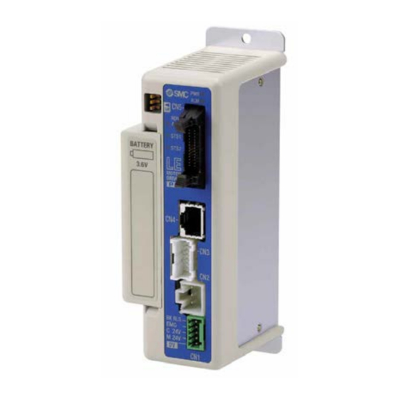
3.2 Parts description Details of the controller are shown below. ① ⑧ ② ⑨ ⑩ ③ ⑪ ⑫ ⑮ ④ ⑬ ⑤ ⑥ ⑦ ⑭ Display Item Details Power supply ON / No alarm: Solid green light Writing data (step data, parameter) / Flashing green light Caution Power supply LED Do not turn off the input power supply for the controller or... - Page 14 Connect to the controller input power supply (DC24V) using the Power supply power supply plug. connector The control power supply (+), stop (+), motor power supply (+), (5 pins) unlocking (+), common (-) Period set switch Sets the backup period. No absolute circuit alarm: Green light on RDY/ALM Ready/ Alarm LED...
-
Page 15: Mounting Method (Mounting Position)
3.3 Mounting method (mounting position) Select the size and the installation style so that the surrounding temperature of the controller is 40°C or less (below 30°C recommended). Mount the controller vertically on the wall as shown below, with 30mm or 50mm or more of space on the top and bottom of the controller. -
Page 16: Preparation For Operation
4. Preparation for Operation 4.1 Charging of the battery The battery built into the controller is fully charged by energizing continuously. The battery charging time will depend on the specifications of the battery used by the customer. STS2 lights up green when 48 hours continuous charging is completed. Caution When the power supply is cut for longer than 1 hour after fully charging the battery, and is applied again, STS2 lights up orange. -
Page 17: Parameter Setting
4.3 Parameter setting Confirm that "2: Absolute" is selected for the setting of "Sensor type" in order to enable the controller absolute function. (Default setting is “2: Absolute”.) Basic parameter details (Items exclusive to absolute controller) Description Input Content Controller Teaching range Software... -
Page 18: Parallel I/O Signal Details
4.4 Parallel I/O signal details ・ I/O cable ・ ・ ・ ・ ・ B13 A13 Connector for CN5 of the controller The end to be connected to a PLC, etc. - Input terminal - Function Description COM+ The terminal for the 24V of the 24VDC I/O signal power. COM- The terminal for the 0V of the 24VDC I/O signal power. - Page 19 motor will be turned OFF. - 18 -...
- Page 20 Effective condition of the Parallel I/O signal Condition SETON SVRE BUSY Signal name SETUP OFF(*1) (Return to origin) DRIVE (Operation start instruction) (“-“ = does not depend on the ON/OFF state of the each output signal) *1 During the positioning operation the SETUP input will be disabled whilst hold is in operation. Caution SETUP and DRIVE can only be accepted during the above conditions.
- Page 21 Function Description Caution continue (1)Pushing operation is finished ,it is automated change to energy saving mode INP output singal is setted to ON. And pushing operation stopped seat is change to running state general power running is repeatedly (Example) Step data“force”is 100% INP(ON) force Step data“Trigger LV”is 80%,...
- Page 22 The table below shows the changes in the output signal with respect to controllers state. Output signal BUSY SVRE Lock SETON OUT0-5 State Lock Controller powered down [SVOFF] with no motion Release Controller powered down [SVON] with no motion Release During returning to origin, [SETUP].
-
Page 23: Operation
5. Operation 5.1 Operation instructions outline This controller can be operated by specifying the step data registered beforehand by parallel I/O signal. For operating procedure other than those unique to the absolute controller, refer to the LECP6* series operation manual “10.1 Operation instruction method”. 5.2 Operation procedure for the absolute controller 1. - Page 24 Caution When you wish to check the hold of the electric gripper, please contact SMC. - 23 -...
-
Page 25: Operation Procedure Of Parallel I/O
5.3 Operation procedure of parallel I/O 5.3.1 When power is supplied for the first time (Including when the battery is completely discharged and when the battery is replaced) - Procedure - -Timing chart- 1) Supply power Power supply ↓ SVON 2) *ESTOP output turns on *ALARM output is turned on once, Input... -
Page 26: 1) Power Supply Is Turned Back On (Normal)
5.3.2 (1) Power supply is turned back on (Normal) If [*ALARM] is ON (no alarm) in T1 after supplying power again, SETON output is ON after T4. - Procedure - -Timing chart- 1) Supply power Power ↓ supply 2) *ESTOP output turns on SVON Input signal... - Page 27 5.3.2 (2) With alarm (group C) when the power is supplied again If [*ALARM] is OFF (alarm is generated) in T1 after supplying power again, SETON output is not ON. In this case, it is necessary to eliminate the cause of the alarm, reset the alarm to turn on SETON output. - Procedure - -Timing chart- 1) Supply power...
-
Page 28: 3) With Alarm (Group D) When The Power Is Supplied Again
5.3.2 (3) With alarm (group D) when the power is supplied again If [*ALARM] is OFF (alarm is generated) in T1 after supplying power again, SETON output is not ON. In this case, it is necessary to eliminate the cause of the alarm, reset the alarm and perform the return to origin position. - Page 29 - 28 -...
-
Page 30: Power Supply Is Cut Due To Alarm (Group E)
5.3.3 Power supply is cut due to alarm (group E) It is necessary to return to origin when alarm (group E) is generated and the alarm is cleared by cutting the power supply. - Procedure - -Timing chart- 1) Supply power Power ↓... -
Page 31: Alarm Detection
6. Alarm detection 6.1 Alarm contents and countermeasures This product outputs a signal to distinguish the type of the alarm when an alarm is generated. Alarms are classified into 5 groups. When an alarm is generated, it is output in OUT0 to 3. Refer to the table below for the combination of the alarm group and the output terminals. - Page 32 * Alarms for absolute controller (Please refer to Alarm Teaching Alarm Description Clear Condition / Countermeasure (code) Description method <Condition> The step data is incorrect for the following conditions (Assignable value range) ① Area1 < Area2 (If both Area1 and Area2 is 0, the alarm will not be activated.) ②...
- Page 33 Alarm Teaching Alarm Description Clear Condition / Countermeasure (code) Description method <Condition> Generated when the step data No. which is not registered is commanded to start. registered Command Step No. RESET the operation incorrect input <Countermeasure> Make sure that the “Movement MOD” of data No.
- Page 34 Alarm Teaching Alarm Description Clear Condition / Countermeasure (code) Description method <Condition> Battery is not connected to the controller Alarm_Com Battery is not Input ment_104 <Countermeasure> Check the connection of the battery connected RESET (1-104) Caution Absolute ID not match (Initial condition) alarm is generated before this alarm.
- Page 35 Alarm Teaching Alarm Description Clear Condition / Countermeasure (code) Description method <Condition> The motor power supply voltage detected in the controller is out of specified range. The controller check the lower limit of the motor power supply voltage only when the servo ON is commanded. <Countermeasure>...
- Page 36 Alarm Teaching Alarm Description Clear Condition / Countermeasure (code) Description method 2 seconds or <Condition> Failed to reach to the set position within the set more of time limit. delay for RESET Positioning <Countermeasure> Eliminate any obstructions that interfere reaching the Input failure with the actuator movement.
- Page 37 Alarm Teaching Alarm Description Clear Condition / Countermeasure (code) Description method Absolute <Condition> Absolute power supply voltage fell below set power RESET value. suuply Input Low AbPow voltage fell RESET below set SVON value. SETUP <Countermeasure> Even after this measure, if the alarm (1-156) regenerates when the power is reapplied, please contact SMC.
- Page 38 Alarm Teaching Alarm Description Clear Condition / Countermeasure (code) Description method <Condition> Positioning of the polarity is not finished properly. Unable to When the servo motor is turned on (SVON is turned on) first find phase Cycle the time after the power is applied, the actuator needs to move within Polarity power...
-
Page 39: Absolute Controller Specific Product Precautions
7. Absolute Controller Specific Product Precautions Danger (1) Do not disassemble the battery. There can be a short circuit inside/ outside. Over heating, explosion or ignition of the battery can result due to the reaction of the internal chemicals of the battery with air. -
Page 40: Troubleshooting
8. Troubleshooting Refer to the table below for troubleshooting. When none of the causes in the troubleshooting can be confirmed and normal operation is recovered by the replacement of a part, it is presumed that failure is in the product. It is possible that this product is damaged due to the operating conditions (applications), please contact SMC to discuss appropriate measures. - Page 41 Possible Investigation method and Problem Countermeasures cause location of possible causes Check if parameter values are correct. Incorrect Modify the values of the parameters to Reconfirm if appropriate controller is used parameter appropriate ones and test the operation. for the actuator. Temporary voltage drop in the power supply.
-
Page 42: Position/ Speed Troubles
8. 2 Position/ Speed troubles Possible Investigation method and Problem Countermeasures cause location of possible causes If it is a pushing operation, repeat return to origin operations several times to Incorrect origin Check if foreign matter is caught in the check if the actuator returns to the position product by operating the actuator. - Page 43 Temporary voltage drop in the power supply. CN1(EMG terminal for the power supply Possibility of momentary voltage drop due connector) is turned OFF due to the to an inadequate power supply capacity is Voltage drop temporary voltage drop of the power inadequate, or the power supply is inrush supply and the actuator stops.
- Page 44 Revision history TQ0870054-OM002 First edition July 2012 TQ0870054-OM004 Sep/ 2013 Revision LECPF→LECP7 Note) This manual is subject to change without prior notice. © 2013 SMC Corporation All Rights Reserved - 43 -...
Need help?
Do you have a question about the LECP7-XB54 Series and is the answer not in the manual?
Questions and answers