Table of Contents
Advertisement
Advertisement
Table of Contents
Troubleshooting

Subscribe to Our Youtube Channel
Related Manuals for Maipu MP1900X Series


Summary of Contents for Maipu MP1900X Series
- Page 1 MP1900X Series Router Installation Manual V1 . 0...
- Page 3 This Manual may be subject to changes on account of product upgrade or other causes. Maipu reserves the right to revise this Manual without any notice. Subject to the laws and regulations, Maipu Communication Technologies Co., Ltd. shall, under no circumstance,...
- Page 4 Preface Manual Introduction This manual introduces the appearance, hardware, and installation preparation and method of the MP1900X series router, as well as its basic use and daily maintenance in terms of energization & operation, troubleshooting and equipment maintenance. Product Version This manual is applicable to the product versions as below.
- Page 5 MP1900X Series Router Installation Manual Preface Convention of icons and signs Format Description Supplement to or emphasis on the aforesaid. Note: Matters that need attention while installing or operating the equipment, which are important for proper installation and Caution: operation.
- Page 6 Preface MP1900X Series Router Installation Manual The manual matching with the product is as follows: Manual Description MP1900X Series Router Detailed introduction to the methods and steps of Configuration Manual configuring the equipment software functions, with the typical cases made available for reference.
-
Page 7: Table Of Contents
MP1900X Series Router Installation Manual Preface Contents PREFACE ················································································································· II 1 ROUTER INTRODUCTION ··················································································· 1-1 1.1 MP1900X-12-AC A ········································· 1-1 PPEARANCE AND ARDWARE TRUCTURE 1.2 MP1900X-22-AC A ········································· 1-2 PPEARANCE AND ARDWARE TRUCTURE 1.3 P MP1900X S ·················································· 1-3 ANEL... - Page 8 Preface MP1900X Series Router Installation Manual 4.1 L ······························································································ 4-1 OG INTO OUTER 4.1.1 C ··················································································· 4-1 ONNECT ONSOLE ABLE 4.1.2 S PC H ····································································· 4-2 YPER ERMINAL ARAMETERS 4.1.3 P ························································································· 4-6 OWER ON AND TART 4.1.4 C ····················································································· 4-7...
- Page 9 MP1900X Series Router Installation Manual Preface A1 Power Consumption/Dimension/Weight······································································· A-1 B Specifications of General Interfaces ············································································· B-1 B1 10Base-T/100Base-TX/1000Base-T-RJ45 Electrical Interface Attributes ································· B-1 B2 1000Base-X-SFP Optical Interface Attributes ································································ B-2 B3 USB Interface Attributes ························································································· B-2 B4 CONSOLE Port Attributes ······················································································ B-3 B5 Micro USB Interface Attributes ·················································································...
- Page 10 Preface MP1900X Series Router Installation Manual E1 Console Cables ···································································································· E-1 E2 GE Ethernet Interface Cable ····················································································· E-2 F Environmental Substance Statement ··············································································· E-2 viii copyright2019 Maipu, all rights reserved...
- Page 11 MP1900X Series Router Installation Manual Preface Figure 1-1 T MP1900X-12-AC ................ 1-1 IGURE HE FRONT APPEARANCE DIAGRAM OF 1-2 T MP1900X-12-AC ................1-2 IGURE HE REAR APPEARANCE DIAGRAM OF 1-3 T MP1900X-22-AC ................ 1-2 IGURE HE FRONT APPEARANCE DIAGRAM OF 1-4 T MP1900X-22-AC ................
- Page 12 Preface MP1900X Series Router Installation Manual 6-1 L ........................6-1 IGURE OOSEN THE CAPTIVE SCREW 6-2 U ..................... 6-2 IGURE NINSTALL THE INTERFACE DAUGHTER CARD 6-3 I ....................6-2 IGURE NSTALL THE INTERFACE DAUGHTER CARD 6-4 F ..........................6-3 IGURE...
- Page 13 MP1900X Series Router Installation Manual Preface Appendix Figure D-1 D ............... D-7 PPENDIX FIGURE IAGRAM OF ROUTER EQUIPOTENTIAL CONNECTION E-1 C ........................E-1 PPENDIX FIGURE ONSOLE CABLE copyright2019 Maipu, all rights reserved...
- Page 14 Preface MP1900X Series Router Installation Manual Table 1-1 I MP1900X ............. 1-3 ABLE NTERFACES ON THE FRONT PANEL OF SERIES ROUTER 1-2 T ....................1-4 ABLE HE MEANINGS OF THE PANEL INDICATORS 1-3 P MP1900X ....................1-5 ABLE OWER MODULES SUPPORTED BY 4-1 T ..............
- Page 15 MP1900X Series Router Installation Manual Preface E-1 C ............... E-1 PPENDIX ABLE ONNECTION RELATIONSHIP OF THE CONSOLE CABLE E-4 C GE E RJ45 ........E-2 PPENDIX ABLE ONNECTION TABLE OF THE THERNET INTERFACE CABLE F-1 T ............E-2 PPENDIX ABLE...
-
Page 17: Router Introduction
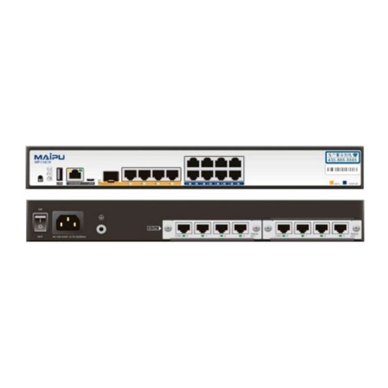
MP1900X Series Router Installation Manual Router Introduction Router Introduction MP1900X series router is a desktop access router independently developed by Maipu, which includes product models: MP1900X-12-AC MP1900X-22-AC. This chapter mainly describes the specifications of MP1900X series router. 1.1 MP1900X-12-AC Appearance and Hardware Structure The dimension of MP1900X-12-AC is 340mm ×... - Page 18 Router Introduction MP1900X Series Router Installation Manual Figure 1-2 The rear appearance diagram of MP1900X-12-AC 1. Fan outlet 2. Power switch 3. Power socket 4. Grounding screw 5.S1 slot of RM2B interface sub card 6.S2 slot of RM2B interface sub card 1.2 MP1900X-22-AC Appearance and Hardware Structure...
-
Page 19: Panel Specifications Of
6.S2 slot of RM2B interface sub card 1.3 Panel Specifications of MP1900X Series Router The interface description is as shown in the following table: Table 1-1 Interfaces on the front panel of MP1900X series router Interface Name Description Reset function button... -
Page 20: Air Passage Of
Flash: indicates that data is transmitted over the port. 1.4 Air Passage of MP1900X Series Router The air flow direction of MP1900X series router chassis is left in and right out, and the diagram is as follows: copyright2019 Maipu, all rights reserved... -
Page 21: Power Module Of
Avoid placing the device with left outlet adjacently above and below the router. 1.5 Power Module of MP1900X Series Router The back panel of MP1900X series router provides one power input. MP1900X-12-AC and MP1900X-22-AC are fixed with one power. The power model and function description are as follows:... -
Page 23: Installation Preparations
When the router is delivered, there is the packing list. Please confirm whether the accessories are complete and good according to the items in the packing list. If there is damaged or loss, please contact Maipu technical staff to replace. 2.1 Check Router Running Environment MP1900 series routers must be used indoors. -
Page 24: Electrical Safety
Installation Preparations MP1900X Series Router Installation Manual 2.2.2 Electrical Safety Please check whether there are potential dangers. For example, the power is not grounded, power supply grounding is not reliable, and the ground is wet. Before moving the router, be sure to remove all external cables (including power cable). -
Page 25: Laser Safety
Figure 2-1 Using method of anti-static wrist 2.2.4 Laser Safety For the MP1900X series router with the optical interface, avoid directly viewing the laser beam from the optical module inside. Viewing the laser beam from the optical module inside directly may damage your eyes. -
Page 26: Open -Package Andi
Multimeter 2.4 Open-Package and Inspection MP1900X series router adopts the carton packaging. The package comprises the carton, plastic bags, protection EPE and other packaging materials. The open-package steps are as follows: Step 1: View the carton label, and confirm the router model in the carton. -
Page 27: Router Installation
Do not place heavy things on the router. 3.1.2 Install Router to Cabinet This section describes how to install the MP1900X series router to the 19-inch standard cabinet. Installation Preparations MP1900X series router is 1U high, so ensure that enough installation space is reserved for the router. - Page 28 Router Installation MP1900X Series Router Installation Manual section. Besides the slide, a tray also can be used to support the router. The installation process of the slide is the same as that of the tray. Therefore, the tray installation process is omitted in this installation manual.
- Page 29 MP1900X Series Router Installation Manual Router Installation cabinet. Step 2: Install the slide on the two sides, respectively. The slides installed on the both sides must be at the same height. Then, tighten the fixing screws. The appearance and installation methods of different cabinets and slides may vary.
- Page 30 Router Installation MP1900X Series Router Installation Manual Before installing the router to the cabinet, ensure that the corresponding positions on the cabinet are installed with slide (tray) and the slide (tray) can support the weight of router and its accessories.
- Page 31 MP1900X Series Router Installation Manual Router Installation The hanging ear does not bear the weight. Do not bear the router only using a hanging ear without installing the slide (tray). Check the Installation After the router is installed to the cabinet, check the installation based on the following items and ensure all the items are normal.
- Page 32 Router Installation MP1900X Series Router Installation Manual Step 4: Use the same method to install the other side of the ground cable to the grounding terminal of the cabinet. Figure 3-4 Connect the ground cable If there is no appropriate grounding point on the cabinet, we also can connect the grounding cable of the router to other grounding bar of the installation place.
- Page 33 MP1900X Series Router Installation Manual Router Installation Figure 3-5 The power SPD 1.Socket Connects the router power. 2.Normal work indicator on: indicates that the circuit is running normally. (green) Off: indicates that the protection circuit is damaged. 3.Grounding polarity on: indicates the wiring error (the PE is not connected...
- Page 34 Router Installation MP1900X Series Router Installation Manual Step 1: Cut short the PE of the port lightning protector based on the distance of the router ground terminal or the lightning protection ground copper bar in the equipment room. Tighten the PE of the port lightning protector securely to the router ground terminal or the lightning protection ground copper bar in the equipment room.
- Page 35 MP1900X Series Router Installation Manual Router Installation 3.4 Connect Power Cable 3.4.1 Installation Preparations Considering the lightening protection requirement of the router, it is recommended that the AC power reaches the better lightening protection effect via the external lightening equipment when bringing in the router.
- Page 36 Router Installation MP1900X Series Router Installation Manual Check and ensure that the power cable is connected correctly. Check and ensure that the interface daughter card is installed and well-contacted. 3-14 copyright2019 Maipu, all rights reserved...
- Page 37 MP1900X Series Router Installation Manual Power on and Run Router Power on and Run Router 4.1 Log into Router When logging into the router for the first time, you can only log into the router via Console port. This is the most basic mode of logging into the router and also the basis of configuring other login modes.
-
Page 38: Set Pc Hypert
Power on and Run Router MP1900X Series Router Installation Manual Figure 4-1 Console cable For details about the inner signal connection of the Console cables, refer to Appendix E1 Console Cable. Figure 4-2 Connect the router and PC via the Console port ... - Page 39 MP1900X Series Router Installation Manual Power on and Run Router Figure 4-3 “Location information” interface Step 2: Display the following Telephone and Modem interface and click OK. Figure 4-4 The Telephone and Modem interface Step 3: Display the following Connection Description interface, and fill in the name in Name (N), such as test, and click OK.
- Page 40 Power on and Run Router MP1900X Series Router Installation Manual Figure 4-5 “Connection Description” interface Step 4: Display the following Connect to interface, select the serial interface used by the connection in the Connect using, and click OK. Figure 4-6 “Connect to” interface...
- Page 41 MP1900X Series Router Installation Manual Power on and Run Router Figure 4-7 “com* Properties” interface Step 6: Display the following test-HyperTerminal interface, and click Properties. Figure 4-8 “test-HyperTerminal” interface Step 7: Display the following “test properties” interface, click Setting, select VT100 in Terminal emulation, and click OK.
-
Page 42: Power On And Start
Power on and Run Router MP1900X Series Router Installation Manual Figure 4-9 “Test properties” interface Step 8: Display the following test-HyperTerminal interface, press Enter at the blank place, and the serial port displays the print information. The setting of the HyperTerminal is complete. -
Page 43: Check After Power On
MP1900X Series Router Installation Manual Power on and Run Router Appendix C2 Requirements for Power Supply. The configuration cable is connected correctly; the PC for configuration is enabled; the setting of the terminal parameters is complete. Before the router is powered on, confirm the position of the power router of the equipment room where the router is located, so as to cut off the power in time when there is an accident. -
Page 44: Access Network
Power on and Run Router MP1900X Series Router Installation Manual Indicator Name Indicator Color Description Green On: The USB device works normally Off: No USB device is inserted or the USB device is removed Flash: The USB device is transmitting data 4.2 Access Network... - Page 45 MP1900X Series Router Installation Manual Power on and Run Router Figure 4-11 Appearance of the LC fiber connector Install Optical Module The MP2900 router only supports the SFP optical module and the SFP optical module is installed as follows: ...
- Page 46 Power on and Run Router MP1900X Series Router Installation Manual Figure 4-13 SFP module Figure 4-14 Install the SFP module When installing the fiber, do not pull out the protection rubber stopper on the SFP module. For unused optical interfaces, please do not unplug the dust plug on the optical interface of the router.
- Page 47 MP1900X Series Router Installation Manual Power on and Run Router Figure 4-15 Remove the optical dust cap Step 3: Remove the dust cap of the SFP module. Figure 4-16 Remove the dust cap of the SFP module Step 4: Insert the prepared fibers to the ports of the optical module in order.
-
Page 48: Hardware Management
This section describes various hardware management functions of the MP1900X series router. With the function interfaces, the user can conveniently view the software and hardware version information of the MP1900X series router, as well as the work status information of the hardware modules. -
Page 49: View Power Status
MP1900X Series Router Installation Manual Power on and Run Router Table 4-2 Key field description of the information displayed via show version Field Description System ID System ID, provided by the device supplier, such as 00017a93651b Hardware Model The router name and the configured... -
Page 50: View Systeme
You can use the show system fan command to view the information of the fan used on the MP1900X series router, including the fan location information, fan speed, fan work status, swapping times of the fan module, and the error times during swapping. -
Page 51: View Swappableo
Power on and Run Router 4.3.5 View Swappable Optical Module Information You can use the show optical all command to view the work parameters of all optical modules used on MP1900X series router. Command: router#show optical all Display as follows:... -
Page 53: Troubleshooting
MP1900X Series Router Installation Manual Troubleshooting Troubleshooting 5.1 Troubleshooting of Configuration System After the router is powered on and if the system is normal, the start information is displayed on the configuration terminal. If the configuration system fails, there may be no display or messy code on the configuration terminal. -
Page 54: Troubleshooting About No
Off: indicates that the fan works abnormally. When the fan indicator on the panel of the MP1900X series router is off, it indicates that the system fan is faulty. Troubleshoot the faults according to the following steps. Step 1: Check whether the power works normally. -
Page 55: Get Technicals
MP1900X Series Router Installation Manual Troubleshooting handling. 5.4 Get Technical Support If the fault remains via the above contents of the chapter, please contact the agent or local technical engineers in time. Before you contact the customer service, please prepare the following information, which is convenient for the customer service staff to help you solve the problem. -
Page 57: Router Maintenance
Router Maintenance Router Maintenance 6.1 Change Interface Daughter Card The interface daughter card of MP1900X series router is the RM2B card. The interface daughter card of MP1900X series router does not support hot-swap. Step 1: Power off the router. - Page 58 Router Maintenance MP1900X Series Router Installation Manual Figure 6-2 Uninstall the interface daughter card Step 4: Put the uninstalled interface daughter card on the anti-static mat or the initial packaging box. Step 5: Push a new interface daughter card along the slot guide slowly and horizontally until the panel of the interface daughter card has a distance of about 1cm to the panel of the service card.
-
Page 59: Change Swappable
Figure 6-4 Fix the captive screw 6.2 Change Swappable Optical Module MP1900X series router only supports the SFP module. The following describes how to change the SFP module. When installing or uninstalling the SFP module, do not use the hands to touch the ... - Page 60 Router Maintenance MP1900X Series Router Installation Manual packaging box, as shown in the following figure. Figure 6-6 Install the dust cap of the SFP module Step 4: Up-turn the handle of the installed SFP module to the vertical position to lock the buckle at the top of the module.
- Page 61 It is suggested not to insert the SFP module with the fiber into the slot directly. Please first pull out the fiber and then install. 6.3 De-dust the Router This section describes how to de-dust the MP1900X series router. The de-dusting mainly refers to the air inlet, outlet, swappable interface daughter card, and pigtail of the router.
-
Page 62: D E - Dust The Interface
Router Maintenance MP1900X Series Router Installation Manual and ventilation for the router. During the router operation, the fan vanes in the fan module will absorb the dust in the around air. When the amount of the dust reaches a certain degree, the dust will affect the stable running of the fan module and will also be the pollution source of other service boards on the router. -
Page 63: D E - Dust Opticali
MP1900X Series Router Installation Manual Router Maintenance There are many methods to de-dust the interface daughter card. However, the overall principle is that the physical and electrical specifications of the interface daughter card cannot be damaged. When using a vacuum cleaner, use a clean and dry anti-static soft brush to gently... - Page 64 Router Maintenance MP1900X Series Router Installation Manual Before de-dusting the optical interface, remove the corresponding interface daughter card at first and ensure that the normal deployment of the system service will not be affected. For the high-power laser interface, use the cleaning tool and material for cleaning.
-
Page 65: Appendix
MP1900X Series Router Installation Manual Appendix Appendix A Entire Router and Common Module Specifications A1 Power Consumption/Dimension/Weight Appendix Table A-1 Power consumption and dimension Model Power Consumption Dimension MP1900X-12-AC 340mm×260mm×44.2mm (W×D×H) MP1900X-22-AC 340mm×260mm×44.2mm (W×D×H) Appendix Table A-2 Router weight Model... -
Page 66: B2 1000Base-X-Sfp Optical Interface Attributes
Appendix MP1900X Series Router Installation Manual Attribute Description Connector type RJ45 Work mode 10Mbps/100Mbps/1000Mbps Half-duplex/full-duplex/auto-negotiation Maximum transmission distance 100m Connection cable Straight-through network cable: C1212-1002 Cross network cable: C1212-1003 B2 1000Base-X-SFP Optical Interface Attributes Appendix Table B-2 1000Base-X-SFP Attribute Description Interface standard IEEE 802.3ab... -
Page 67: B4 Console Port Attributes
MP1900X Series Router Installation Manual Appendix Attribute Description (it can be pulled out after un-installing the USB device via the command) Cables B4 CONSOLE Port Attributes Appendix Table B-4 CONSOLE Port attributes Attribute Description Interface standards Asynchronous EIA/TIA-232 Connector type... -
Page 68: C1.2 Humidity Requirement
Appendix MP1900X Series Router Installation Manual following table. Appendix Table C-1 Work temperature requirements Description Temperature Storage environment temperature -20°C–70°C Work condition 0°C–45°C If the temperature is too high, the reliability of the router reduces greatly. The long-time high temperature affects the router life and speeds up the aging of insulation materials. -
Page 69: C1.3 Cleanliness Requirements
MP1900X Series Router Installation Manual Appendix easily, too. If the relative humidity in the equipment room is too low, insulation pads shrink, which causes the fastened screws loose. Meanwhile, in dry environment, static electricity appears easily, which harms the circuits on the router. -
Page 70: C1.4 Anti-Interference Requirement
Appendix MP1900X Series Router Installation Manual Max. (mg/m 0.01 C1.4 Anti-Interference Requirement The various interference sources no matter from the exterior of the router or from the interior router affect the router through capacitance coupling, inductance coupling, electromagnetic radiation, public impedance (including grounding system) coupling, and lead (such as power cables, signal lines and output lines). -
Page 71: C2.2 Suggestions On Fundamental Ac Power Supply
MP1900X Series Router Installation Manual Appendix than 10 ms. Otherwise, the router may restart or reset. The AC capacity of the equipment room should consider the work current and faulty current of the router. Ensure that the independent router has the independent AC power distribution protection device. -
Page 73: D Router Grounding Specifications And Protection
MP1900X Series Router Installation Manual Appendix D Router Grounding Specifications and Protection D1 Router Grounding Specifications Grounding specifications include general grounding specification, grounding specification for the building of equipment rooms, router grounding specification, communication power grounding specification, signal cable grounding specification, and ground cable laying specification. -
Page 74: D1.4 Grounding Specifications For Communication Power
Appendix MP1900X Series Router Installation Manual Description The router protection ground (PGND) shall be short-circuited nearby to the protection grounding cooper bar provided by the user, with the short-circuiting cable of the yellow/green plastic insulated copper conducting wire above 35mm... -
Page 75: D1.5 Laying Specifications Of Signal Cable
MP1900X Series Router Installation Manual Appendix Description The DC power shall be added the protection circuit against surge. D1.5 Laying Specifications of Signal Cable The laying specifications of the signal cable are shown in the following table: Appendix Table D-4 The laying specifications of the signal cable... -
Page 76: D2 Router Protection
Appendix MP1900X Series Router Installation Manual Description The length of the protection ground wire should not exceed 45 m, but should be as short as possible. When exceeding 45m, it is required that the consumer re-sets the ground bar nearby. -
Page 77: D2.2 Installation Method Of Cable Wiring
MP1900X Series Router Installation Manual Appendix If using the shielded cable, ensure that the shielded layer well contacts with the metal shell of the router at the router interface. We should install the signal arrester at the corresponding interface of the router after the cable enters the indoor. - Page 78 Appendix MP1900X Series Router Installation Manual only and you also need to wipe the surface of the peer fiber connector. When connecting, you cannot twist or bend the fiber. After installation, the bent radius of the fiber cannot be smaller than 40 mm (In dynamic bending case, the minimum bend radius is 20 D;...
-
Page 79: D2.3 Equipotential Connection Method
MP1900X Series Router Installation Manual Appendix D2.3 Equipotential Connection Method The interconnected routers in the same work range need the equipotential connection. For example, the interconnected routers, the metal sheath of the cable, power supply PE line, and the installed metal structure should ensure the equipotential connection. -
Page 81: E Cables
Connected to the nine-core serial interface socket of the PC, the console cable of the MP1900X series router is an eight-core unshielded cable. The one side of the cable is the crimping RJ-45 crystal plug and the other side is a DB9 (hole). The view of the console cable is shown in the following figure. - Page 82 MP1900X Series Router Installation Manual E2 GE Ethernet Interface Cable The GE Ethernet interface cable of the MP1900X series router is an eight-core unshielded twisted cable. Port 1 and port 2, port 3 and port 6, port 4 and port 5, and port 7 and port 8 consist of four pairs of bidirectional receiving and transmitting difference cable pairs.
- Page 83 For the use conditions of the product in the environmental protection use period, refer to the requirements for the use environment in the product manuals. In the statement, list all components that may be configured in Maipu products. For the actual components contained in each product, please prevail in kind. ...
Need help?
Do you have a question about the MP1900X Series and is the answer not in the manual?
Questions and answers