Table of Contents
Advertisement
Advertisement
Table of Contents
Troubleshooting

Subscribe to Our Youtube Channel
Related Manuals for Maipu MP1800X-40


Summary of Contents for Maipu MP1800X-40
- Page 1 MP1800X Series Router Installation Manual V1 .0...
- Page 3 This Manual may be subject to changes on account of product upgrade or other causes. Maipu reserves the right to revise this Manual without any notice. Subject to the laws and regulations, Maipu Communication Technologies Co., Ltd. shall, under no circumstance,...
-
Page 4: Preface
& operation, troubleshooting and equipment maintenance. Product Version This manual is applicable to the product versions as below. Product name Product Version MP1800X series router MP1800X-40 MP1800X-40W MP1800X-40E MP1800X-50 Target Users The major target users of this Manual are: ... - Page 5 Preface MP1800X Series Router Format Description Keywords of Screen print Key information of screen output (red part) Convention of icons and signs Format Description Supplement to or emphasis on the aforesaid. Note: Matters that need attention while installing or operating the equipment, which are important for proper installation and Caution: operation.
- Page 6 Technical Support Technical support hotline: 400-65710935 & 400-886-8669 Email (feedback): support@maipu.com Revision History The Revision History is the summary of all manual updates. The latest version includes all previous updates. Version Revision...
-
Page 7: Table Of Contents
1.1.1 MP1800X-40 · · · · · · · · · · · · · · · · · · · · · · · · · · · · · · · · · · · · · · ·... - Page 8 Preface MP1800X Series Router Installation Manual 4.1.3 E · · · · · · · · · · · · · · · · · · · · · · · · · · · · · · · · · · · · · · · · · · · · · · · · · · · · · · · · · · · · · · · · · · · · · · · · · · · · · · · · · · · · · · · · · · · · · · · · · 4-5 NERGIZATION 4.1.4 P ·...
- Page 9 Preface MP1800X Series Router C4 4G Antenna · · · · · · · · · · · · · · · · · · · · · · · · · · · · · · · · · · · · · · · · · · · · · · · · · · · · · · · · · · · · · · · · · · · · · · · · · · · · · · · · · · · · · · · · · · · · · · · · · · · · · · · · C-3 D Requirements for Equipment Operating Environment ·...
- Page 10 Preface MP1800X Series Router Installation Manual Figures 1-1 MP1800X-40 ........................1-1 IGURE APPEARANCE 1-2 MP1800X-40W ........................1-2 IGURE APPEARANCE 1-3 MP1800X-40E ........................1-3 IGURE APPEARANCE 1-4 MP1800X-50 ........................1-4 IGURE APPEARANCE 1-6 P ........................1-4 IGURE OWER ADAPTER APPEARANCE 2-1 U .........................
- Page 11 Preface MP1800X Series Router Appendix Figures A-1 AD24-1S0N ....................A-3 PPENDIX IGURE POWER ADAPTER C-1 T ................... C-1 PPENDIX IGURE HE DIAGRAM OF THE CONSOLE CABLE C-2 RJ45 ..........................C-2 PPENDIX IGURE BASE C-3 WIFI ......................... C-3 PPENDIX IGURE ANTENNA C-4 4G ..........................
- Page 12 MP1800X Series Router Installation Manual Tables 4-1 MP1800X-40E ....................4-6 ABLE INDICATOR DESCRIPTION 4-2 MP1800X-40W ....................4-8 ABLE INDICATOR DESCRIPTION 4-3 MP1800X-40/SJW12-4G .................. 4-9 ABLE INDICATOR DESCRIPTION 4-4 MP1800X-50 ..................... 4-11 ABLE INDICATOR DESCRIPTION 4-5 T ABLE HE DESCRIPTION FOR THE KEY FIELDS OF THE INFORMATION DISPLAYED BY THE SHOW VERSION ................................
- Page 13 Preface MP1800X Series Router Appendix Tables A-1D ........................... A-2 PPENDIX TABLE IMENSION B-1 C ..................... B-4 PPENDIX ABLE ONSOLE PORT PROPERTIES B-2 T -T/100B -TX/1000B -T RJ45 PPENDIX ABLE HE PROPERTIES OF THE ELECTRICAL ................................B-4 INTERFACE B-3 USB ....................B-5 PPENDIX ABLE INTERFACE PROPERTIES...
-
Page 15: Product Introduction
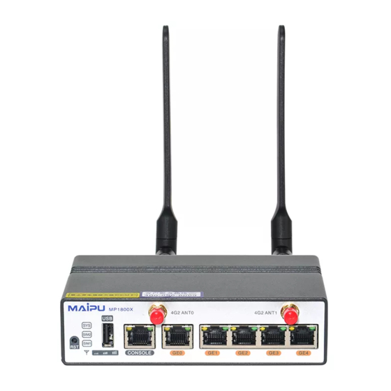
EVDO, CDMA 1x, GSM network. The dual SIM card slots can be switched via the DIP switch. The device adopts the 12V/24W power adapter to provide power. MP1800X-40 dimension is 145 x 100 x 38mm (W x D x H). Figure 1-1 MP1800X-40 appearance 1. -
Page 16: Mp1800X-40W
Product Introduction MP1800X Series Router Installation Manual 9. System power status indicator 10. SIM card DIP switch 11. SMI card switching description 12. 4G antenna 13. Grounding screw 1.1.2 MP1800X-40W MP1800X-40W router supports one console port, one USB interface, five 10M/100M/1000M Ethernet ports, supports TD-LTE, FDD-LTE, TD-SCDMA, WCDMA, EVDO, CDMA 1x, and GSM network, and supports WIFI(IEEE 802.11b/g/n). -
Page 17: Mp1800X-40E
Product Introduction MP1800X Series Router 1.1.3 MP1800X-40E MP1800X-40E router supports one console port, one USB interface, five 10M/100M/1000M Ethernet ports, supports TD-LTE, FDD-LTE, TD-SCDMA, WCDMA, EVDO, CDMA 1x, and GSM network, and supports dual 4G and dual-card dual-standby . The device adopts the 12V/24W power adapter to provide power. MP1800X-40E dimension is 145 x 100 x 38mm (W x D x H). -
Page 18: Power Introduction
8. Grounding screw 1.2 Power Introduction MP1800X-40, MP1800X-40W, MP1800X-40E, SJW12-4G adopt the external power adapter AD24-1S0N to provide the power. The output voltage of the power adapter is 12V and the output power is 24W. MP1800X-50 adopts the inbuilt fixed power, and is connected with the external electric power supply. -
Page 19: Installation Preparation
The equipment is accompanied with Packing List. Please verify whether the accessories are complete and in good conditions accordingly. In case of any damage or omission, please contact Maipu’s technical support without delay to request a replacement. 2.1 Operating Environment Inspection 2.1.1 Machine Room Inspection... -
Page 20: Safety Precautions
Installation Preparation MP1800X Series Router Installation Manual Caution: Please refer to “Appendix A Specifications of the Router and Common Modules” for details on the power consumption of the router. 2.2 Safety Precautions 2.2.1 General Safety Caution: The floor of the installation site shall be dry and smooth, with the anti-skid measures in place. -
Page 21: Installation Tools
Installation Preparation MP1800X Series Router Caution: For safety sake, please check the resistance of the ESD wrist. The resistance between human body and ground shall be 1-10 megohm. The steps to use the ESD wrist are as follows: Step 1: Put your hand into the ESD wrist. Step 2: Pull tightly the lock catch and ensure that the sheet metal of the ESD wrist well contact with your skin. -
Page 22: Unpacking Inspection
Installation Preparation MP1800X Series Router Installation Manual Optional cable Equipment and instruments: Configurable terminal (a common PC or a laptop) Multimeter 2.4 Unpacking Inspection The unpacking steps of MP1800X series router are as follows: Step 1: View the carton label, and confirm the device model in the carton. Step 2: Check whether the goods in the carton are complete. -
Page 23: Router Installation
MP1800X Series Router Router Installation 3.1 Example 1 of Installing Router In example 1, describe installing MP1800X-40, MP1800X-40W, MP1800X-40E, SJW12-4G router on the horizontal plane, table surface environment or vertical surface, upright column and other vertical environment. Select the correct installation mode according to the actual installation environment. -
Page 24: Install The Routerv
Router Installation MP1800X Series Router Installation Manual Figure 3-2 The diagram of the desktop fixing 3.1.2 Install the Router Vertically The equipment can be fixed on the vertical surface of the wall, cabinet, and other installation environment by screws. Purchase expansion screws or OTC screws according to the installation environment. -
Page 25: Install Router Tow
Router Installation MP1800X Series Router Install the router to the workbench. Install the router to the cabinet. 3.2.1 Install Router to Workbench Place the router on the clean workbench. During the installation, pay attention to the following: Ensure the stability and well-grounding of the workbench. ... -
Page 26: Figure 3-4 The Minimum Height Of The Tray
Router Installation MP1800X Series Router Installation Manual Figure 3-4 The minimum height of the tray The following describes how to install a tray to the 19-inch standard cabinet. The installation steps of the tray are as follows: Step 1: Ensure the installation position of the tray on the cabinet and mark the installation hole position using a marker. -
Page 27: Figure 3-5 Install The Floating Nuts
Router Installation MP1800X Series Router column, with the expected position marked with a marking pen. Step 2: Install the floating nuts at the marked position (A floating nut must be installed on each installation hole on the hanging ear.) Figure 3-5 Install the floating nuts Installing the Router to the Cabinet Caution: ... -
Page 28: Figure 3-6 Install The Router To The 19-Inch Standard Cabinet
Router Installation MP1800X Series Router Installation Manual Figure 3-6 Install the router to the 19-inch standard cabinet Note: If the screw hole on the hanging ear cannot align to the floating nut installed on the cabinet correctly, check whether the bearing surface of the tray is on the integer U boundary and whether the floating nut is installed on the correct hole position. -
Page 29: Energization And Operation
Energization and Operation MP1800X Series Router Energization and Operation 4.1 Equipment Login The Console port is the only approach to log into the equipment for the first time, which is the basic log-in mode and the only way to configure other log-in modes. 4.1.1 Connecting the Configuration Cable The MP1800X router has a serial port (EIA/TIA-232), through which, the PC (or laptop) with RS-232 serial port may be used to configure the router. -
Page 30: Setting Theh
Energization and Operation MP1800X Series Router Installation Manual used to connect with the PC (or laptop), as shown in Figure 4-1. Caution: Matters that need attention while installing or operating the equipment, which are important for proper installation and operation. ... -
Page 31: Figure 4-3 The Telephone And Modem Interface
Energization and Operation MP1800X Series Router Figure 4-3 The Telephone and Modem interface Step 3: Display the following Connection Description interface, and fill in the name in Name (N), such as test, and click OK. Figure 4-4 “Connection description” interface Step 4: Display the following Connect to interface, select the serial port used by the connection in the Connect using, and click OK. -
Page 32: Figure 4-6 The Com1 Properties Interface
Energization and Operation MP1800X Series Router Installation Manual Step 5: Display the following COM1 Properties interface, set the baud rate as 9600, data bit as 8, parity check as none, stop bit as 1, and data flow control as none, and then click OK. Figure 4-6 The COM1 Properties interface Step 6: Display the following test-HyperTerminal interface, and click Properties. -
Page 33: Energization
Energization and Operation MP1800X Series Router Figure 4-8 “Test properties” interface Step 8: Display the following test-HyperTerminal interface, press Enter at the blank place, and the serial port displays the print information. The setting of the HyperTerminal is complete. Figure 4-9 The test-Hyperterminal interface after setting 4.1.3 Energization Pre-energization Inspection The pre-energization inspection for the router includes:... -
Page 34: Post-Energization Inspection
Energization and Operation MP1800X Series Router Installation Manual Caution: Before energizing the router, it is required to check the power supply switch in the machine room where the switch is located, in order to cut off the power supply immediately in case of an accident. - Page 35 Energization and Operation MP1800X Series Router Indicator Type Indicator Indicator Color Status Name System status Green Flash quickly (5Hz flash indicator frequency): hardware starts work after energization Flash slowly (0.5Hz flash frequency):The system works normally On/off: system works abnormally Power status Green On: The power works normally...
-
Page 36: Mp1800X-40W Indicator Description
Energization and Operation MP1800X Series Router Installation Manual Indicator Type Indicator Indicator Color Status Name connected or is connected, but the negotiated rate is 10/100M. Green Off: The interface is not linked On: The interface is linked, but there is no data receiving and sending Flash: The interface is linked, and there is data receiving and... -
Page 37: Mp1800X-40/Sjw12-4G Indicator Description
On: The interface is linked, but there is no data receiving and Green sending Flash: The interface is linked, and there is data receiving and sending. Table 4-3 MP1800X-40/SJW12-4G indicator description Indicator Type Indicator Indicator Color Status Name Flash quickly... - Page 38 Energization and Operation MP1800X Series Router Installation Manual Indicator Type Indicator Indicator Color Status Name normally On/off: The system works abnormally On: The power works normally Power status green Off: power works indicator abnormally On: The SIM card of 4G channel 1 is in place Monochrome 4G indicator1...
-
Page 39: Table 4-4 Mp1800X-50 Indicator Description
Energization and Operation MP1800X Series Router Indicator Type Indicator Indicator Color Status Name Off: The interface is not linked On: The interface is linked, but there is no data receiving and Green sending Flash: The interface is linked, and there is data receiving and sending. -
Page 40: Network Access
Energization and Operation MP1800X Series Router Installation Manual Indicator Type Indicator Indicator Color Status Name 10/100M. Off: The interface is not linked On: The interface is linked, but there is no data receiving and Green sending Flash: The interface is linked, and there is data receiving and sending. -
Page 41: Viewing The Software And Hardware Versions Of The Router
MyPower (R) Operating System Software MP1800X-40E(V1) system image file (flash0: /flash/rp37-7.3.0.58(R).pck), version 7.3.0.58(R)(integrity), Compiled on May 12 2017, 10:24:21 Copyright (C) 2014 Maipu Communication Technology Co., Ltd. All Rights Reserved. MP1800X-40E(V1) Version Information System ID : 00017a205314 Hardware Model... -
Page 42: Viewing The System Environment Temperature
Energization and Operation MP1800X Series Router Installation Manual Field Description flash0: /flash/rp37-7.3.0.58(R).pck Compiled Version compile time, such as May 12 2017, 10:24:21 4.3.2 Viewing the System Environment Temperature The temperature information of the main chips on MP1800X series router may be viewed by the show environment command. -
Page 43: Troubleshooting
Troubleshooting MP1800X Series Router Troubleshooting This section describes how to clear the installation errors of the MP1800X series router. 5.1 Configuration System Troubleshooting After energizing the router, the start information may be displayed on the configuration terminal if the system works properly. In case of a configuration system failure, the configuration terminal may display no information or the messy code. -
Page 44: Power Failure Troubleshooting
5. Brief description of the failure 6. Brief description of the troubleshooting measures taken You can call the Customer Service Hotline or seek for help through the website or E-mail. Customer Service Hotline: 028-65710935; 400-886-8669 Website: http://www.maipu.com E-mail: support@maipu.com 5-16 copyright2017Maipu, all rights reserved... -
Page 45: Router Maintenance
Router Maintenance MP1800X Series Router Router Maintenance This chapter describes the changing and maintaining of the device module. 6.1 De-dust the Router This section describes how to de-dust the MP1800X series router. Warning: All de-dusting must be operated based on the anti-static requirements. For example, the staff must wear the anti-static overalls, anti-static wrist, and anti-wrist gloves if they’ll work on the workbench. -
Page 46: Appendix
A Specifications of the Router and Common Modules A1 Dimension/Weight/Power Consumption Appendix table A-1Dimension Model Dimension Width (W) Depth (D) Height (H) MP1800X-40 MP1800X-40W MP1800X-40E SJW12-4G MP1800X-50 44.2 Note: The dimension data is the dimension value of the chassis itself, excluding the dimensions of the hanging ears, wire rack and other field installation parts and accessories after assembly. -
Page 47: A2 Power Adapter Specifications
MP1800X-40W MP1800X-40E SJW12-4G MP1800X-50 A2 Power Adapter Specifications MP1800X-40, MP1800X-40W, MP1800X-40E, and SJW12-4G routers adopt the DC power supply, which is converted to the DC power via the external power adapter. The power adapter has the following specification: Specification Description... -
Page 48: B Specifications Of Common Interfaces
Appendix MP1800X Series Router Installation Manual Item Data Rated input voltage range 100V-240V AC 50/60Hz Max. input voltage range 90V-264V AC 47-63Hz Output voltage Max. output current Max. output power B Specifications of Common Interfaces Describe the properties of the device interface. B1 Console Port Properties Appendix Table B-1 Console port properties Property... -
Page 49: B3 Properties Of Usb Interface
Appendix MP1800X Series Router Property Description Half-duplex/full-duplex/auto negotiation Max. transmission distance 100m Connection cable Twisted pair of Category 5 or above B3 Properties of USB Interface Appendix Table B-3 USB interface properties Property Description Interface standard USB2.0 Interface type USB A Work mode 1.5M, 12Mbps, 480Mbps Host, support direct hot-swap and controlled (command... -
Page 51: C Cable
It is recommended to use Maipu modules on the router. The following information is just for reference. For details, consult Maipu marketing personnel or technical support personnel. C1 Console Cable Connected to the nine-core serial interface socket of the PC, the console cable of the MP1800X series router is an eight-core unshielded cable. -
Page 52: C2 Ethernet Electrical Interface Cable
Appendix MP1800X Series Router Installation Manual RJ45 Signal Direction DB-9 ← ―― ―― ―― ―― C2 Ethernet Electrical Interface Cable The Ethernet interface cable for the MP1800X series router is recommended to be the 8-core straight-through unshielded twisted pair of category 5 or above. Appendix Table C-2 The connection relation of the RJ45 cable (category-5 twisted pair) RJ45 Signal... -
Page 53: C4 4G Antenna
Appendix MP1800X Series Router C3 WIFI Antenna Appendix Figure C-3 WIFI antenna C4 4G Antenna Appendix Figure C-4 4G antenna D Requirements for Equipment Operating Environment D1 Requirements for equipment room environment D1.1 Architectural requirements for equipment room It is recommended to use the ESD floor for the equipment room, to avoid dusting. Generally, the raised ESD floor is required to be laid. - Page 54 0° C~45° C Work humidity 5%~85%/RH, non-condensing Caution: Work temperature 1 indicates the permitted work temperature of MP1800X-40, MP1800X-40W, MP1800X-40E, SJW12-4G. Work temperature 2 indicates the permitted work temperature of MP1800X-50. Excessive temperature will largely reduce the reliability of the router, prolonged high temperature will also affect their lives, and excessive temperature will accelerate the aging of the insulating material.
-
Page 55: D1.3 Cleanliness Requirements
Appendix MP1800X Series Router D1.3 Cleanliness requirements Dust is harmful to the safe operation of the router. When indoor dust falls on the router, it may cause electrostatic adsorption to lead to poor contact of the metal connector or metal contact. In particular, it is easier to cause electrostatic adsorption when the indoor relative humidity is low, which does not only affect the equipment life, but also easily lead to communication failure. -
Page 56: D1.4 Anti-Interference Requirements
Appendix MP1800X Series Router Installation Manual D1.4 Anti-interference requirements There may be certain interference sources during the working of the router. The router is influenced by capacitive coupling, inductance coupling, electromagnetic wave radiation, common impedance (including grounding system) coupling and conducting wires (including power cable, signal cable and output cable, etc.), etc., either from outside of the application system or from inside of the router. -
Page 57: D2.2 Dc Power Requirement
Appendix MP1800X Series Router restart or reset. With regard to the AC distribution capacity in the equipment room, the equipment working current and fault current shall be taken into full account. Independent equipment shall be guaranteed to have independent AC distribution protection device. -
Page 58: D2.3 Suggestions On Fundamental Ac Power Supply
Code for Design of Low Voltage Power Distribution Installations and Wiring Systems (GB50045-95). The devices adopting the DC power supply include MP1800X-40, MP1800X-40W, MP1800X-40E, and SJW12-4G. D2.3 Suggestions on fundamental AC power supply Suggestions on fundamental AC power supply include: ... -
Page 59: E Equipment Grounding Specifications And Protection
Appendix MP1800X Series Router E Equipment Grounding Specifications and Protection E1 Equipment grounding specifications Grounding specifications include general grounding specification, grounding specification for the building of equipment rooms, equipment grounding specification, communication power grounding specification and ground cable laying specification. E1.1 General grounding specifications The general grounding specification is as shown in the following table. -
Page 60: E1.4 Grounding Specifications For Communication Power
Appendix MP1800X Series Router Installation Manual Description Protection ground shall be done for various kinds of communication equipment and corollary equipment (mobile base station, transmission equipment, and power supply, etc.) in the equipment room, and the protection grounds of various kinds of equipment in the station shall be tandem to the same ground busbar, and the protection grounds of different pieces of equipment in same equipment room shall be tandem to the protection ground bar in the same equipment room. -
Page 61: E1.5 Specifications For Ground Cable Laying
Appendix MP1800X Series Router Description less than 20KA. The communication power protection ground shall share a group of ground body with the communication equipment protection ground, and when the communication power and communication equipment are in the same room, they shall share the protection ground bar in the same room. The AC power port shall be added the lightning protection circuit. -
Page 62: E2 Equipment Protection
Appendix MP1800X Series Router Installation Manual E2 Equipment protection This section mainly introduces the matters to be noticed for equipment lightning protection during the installation. E2.1 General requirements for lightning protection cable layout Equipment cables can be divided into indoor cables and outdoor cables according to positions of the connecting terminals. -
Page 63: E2.2 Cabling And Installation Methods
Appendix MP1800X Series Router When outdoor cables without any protection are connected to the equipment, the corresponding port must be added the signal lightning arrester. During cabling of optical fibers, the cabling shall be smooth and optical fibers shall be bundled neatly. -
Page 64: F Environmental Substance Statement
Appendix MP1800X Series Router Installation Manual Device ground terminal Device equipotential bonding line Ground protection cable Ground bar F Environmental Substance Statement Appendix Table F-1 Toxic and harmful substance name and content identification Toxic and harmful substance or element Mercur Cadmiu Hexavale Polybrominat... - Page 65 Appendix MP1800X Series Router The environmental substances or elements contained in the product will not leak or change suddenly in the environment-friendly use period if the use conditions in the environment-friendly use period are strictly followed. The environment-friendly use period of the lithium ion battery of the product is 5 years, and that of other parts is 50 years.
Need help?
Do you have a question about the MP1800X-40 and is the answer not in the manual?
Questions and answers