Table of Contents
Advertisement
Quick Links
Evaluating the ADRF5700, 2 dB LSB, 5-Bit, Silicon Digital Attenuator, 100 MHz to 22 GHz
FEATURES
Full featured evaluation board for the
►
Simple connection to test equipment
►
Through line for calibration
►
EQUIPMENT NEEDED
DC power supplies
►
Network analyzer
►
GENERAL DESCRIPTION
The ADRF5700 is a 100 MHz to 22 GHz, 2 dB LSB, 5-bit digital
attenuator manufactured in the silicon process.
This user guide describes the ADRF5700-EVALZ evaluation board,
which was designed to simply evaluate the features and perform-
ance of the ADRF5700. A photograph of the evaluation board is
shown in
Figure
1.
The ADRF5700 data sheet provides full specifications for the
ADRF5700. Consult the ADRF5700 data sheet in conjunction with
this user guide when using the ADRF5700-EVALZ.
PLEASE SEE THE LAST PAGE FOR AN IMPORTANT
WARNING AND LEGAL TERMS AND CONDITIONS.
ADRF5700
User Guide | EVAL-ADRF5700
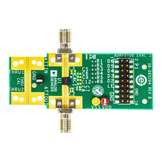
ADRF5700-EVALZ EVALUATION BOARD
PHOTOGRAPH
Figure 1. Evaluation Board Photograph
UG-2152
Rev. 0 | 1 of 8
Advertisement
Table of Contents

Subscribe to Our Youtube Channel
Related Manuals for Analog Devices EVAL-ADRF5700


Summary of Contents for Analog Devices EVAL-ADRF5700
-
Page 1: Features
User Guide | EVAL-ADRF5700 UG-2152 Evaluating the ADRF5700, 2 dB LSB, 5-Bit, Silicon Digital Attenuator, 100 MHz to 22 GHz FEATURES ADRF5700-EVALZ EVALUATION BOARD PHOTOGRAPH Full featured evaluation board for the ADRF5700 ► Simple connection to test equipment ► Through line for calibration ►... -
Page 2: Table Of Contents
User Guide EVAL-ADRF5700 TABLE OF CONTENTS Features..............1 Power Supply and Control Inputs.......3 Equipment Needed..........1 RF Inputs and Outputs ........3 General Description..........1 Test Procedure............5 ADRF5700-EVALZ Evaluation Board Photograph 1 Biasing Sequence..........5 Evaluation Board Hardware........3 Evaluation Board Schematic and Artwork..... 6 Overview............ -
Page 3: Evaluation Board Hardware
User Guide EVAL-ADRF5700 EVALUATION BOARD HARDWARE OVERVIEW POWER SUPPLY AND CONTROL INPUTS The ADRF5700-EVALZ is a connectorized board, assembled with The ADRF5700-EVALZ has two power supply inputs, six control ADRF5700 and its application circuitry. All components are inputs, and a ground, as shown in Table 1. - Page 4 User Guide EVAL-ADRF5700 EVALUATION BOARD HARDWARE Figure 3. Insertion Loss vs. Frequency analog.com Rev. 0 | 4 of 8...
-
Page 5: Test Procedure
User Guide EVAL-ADRF5700 TEST PROCEDURE For third-order intercept point evaluation, use two signal generators BIASING SEQUENCE and a spectrum analyzer. A high isolation power combiner is also To bias up the ADRF5700-EVALZ, perform the following steps: recommended. 1. Ground the GND test point. -
Page 6: Evaluation Board Schematic And Artwork
User Guide EVAL-ADRF5700 EVALUATION BOARD SCHEMATIC AND ARTWORK Figure 5. ADRF5700-EVALZ Evaluation Board Schematic analog.com Rev. 0 | 6 of 8... - Page 7 User Guide EVAL-ADRF5700 EVALUATION BOARD SCHEMATIC AND ARTWORK Figure 6. ADRF5700-EVALZ Evaluation Board Assembly Diagram analog.com Rev. 0 | 7 of 8...
-
Page 8: Ordering Information
Evaluation Board until you have read and agreed to the Agreement. Your use of the Evaluation Board shall signify your acceptance of the Agreement. This Agreement is made by and between you (“Customer”) and Analog Devices, Inc. (“ADI”), with its principal place of business at Subject to the terms and conditions of the Agreement, ADI hereby grants to Customer a free, limited, personal, temporary, non-exclusive, non-sublicensable, non-transferable license to use the Evaluation Board FOR EVALUATION PURPOSES ONLY.
Need help?
Do you have a question about the EVAL-ADRF5700 and is the answer not in the manual?
Questions and answers