Table of Contents
Advertisement
Quick Links
Advertisement
Table of Contents

Subscribe to Our Youtube Channel
Related Manuals for Analytic Systems BCA1505U-24DW


Summary of Contents for Analytic Systems BCA1505U-24DW
- Page 1 INSTALLATION & OPERATION MANUAL BCA1505 SERIES BATTERY CHARGER...
-
Page 2: Battery Charger Precautions
AC SOURCE BATTERY CHARGER IMPORTANT SAFETY INSTRUCTIONS SAVE THESE INSTRUCTIONS — This manual contains important safety and operating instructions for the battery charger. BATTERY CHARGER PRECAUTIONS 1. Do not expose the battery charger to rain or snow unless it is a sealed model. 2. - Page 3 Improper connection can result in the risk of electric shock. MEDICAL EQUIPMENT NOTICE Analytic Systems does not recommend the use of their products in life support applications where failure or malfunction of this product can be reasonably expected to cause failure of the life support device or to significantly affect its safety or effectiveness.
- Page 4 TABLE OF CONTENTS • Front Cover, Product Photo and Title • Product warnings and advisories • Table of Contents • Description/Overview of product • Main Parts • Operation instructions • Mounting Instructions • Connection instructions • Configuration instructions • Options •...
-
Page 5: Box Contents
Box Contents The box you have received should contain the following: • One BCA1505 battery charger • This manual • One Warranty Card If anything is missing or damaged please contact your dealer or Analytic Systems for a replacement... -
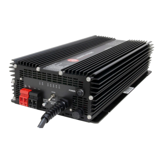
Page 6: Main Parts
Main Parts Front Panel 1. 2 Stage / 3 Stage Select Switch 6. Equalize Start Push button (locking toggle switch) (recessed) 2. Battery Negative Output Connection 7. AC Power Cord 3. Battery Positive Output Connection 8. AC Input Fuse 4. LED Indicators 9. -
Page 7: Operation
Operation This unit is designed for simple and intuitive operation. Before operating, make sure that this unit is properly installed and connected. See Installation for more information. TO CHARGE A BATTERY Choose which type of charging profile will be used during charging by moving the Stage Select switch. -
Page 8: Installation
Installation MOUNTING Mount the unit in a DRY and WELL VENTILATED location with at least 4 inches of clearance all around it. There is 1500 volts of isolation between the input and output, and the input and 3.76 0.25 case. There is 500 volts (1500V for 48V output units) of isolation between the 12.00 output and case. -
Page 9: Dc Output Connection
DC OUTPUT CONNECTION This unit is equipped with two pairs of Phoenix VDFK Through Panel connectors to serve as Output Battery Connections. Use wires of an appropriate gauge for the expected output current to make this connection. #6AWG wiring is the recommended size of wire to use for this connection. -
Page 10: Charging Profiles
Charging Profiles This unit has both two-stage and three-stage charging capability. You can choose which charging profile is used during operation by using the Stage Select switch on the front panel. Below are explanations of the two profiles: TWO-STAGE CHARGING Bulk Float (Constant Current) -
Page 11: Remote Control Accessory
IMPORTANT: This remote is to be used only on Battery Chargers manufactured by Analytic Systems. The remote control panel and 9-pin D-connector are an optional feature for this product line. The remote control panel allows the unit to be operated remotely and duplicates all the diagnostic LED indicators with audible alarm. -
Page 12: Battery Temperature Sensor
BATTERY TEMPERATURE SENSOR CONNECTION This unit is equipped with an Amphenol MIL-Spec PT02A8-4S connector to connect to up to two Analytic Systems waterproof battery temperature sensor(s). This connection’s wiring is shown on the unit’s label. There are multiple ways to install the sensor at the battery. Regardless of which method you use, the sensor must be firmly secured to the battery. - Page 13 TO PERFORM AN EQUALIZE CYCLE: Connect and install the supplied Analytic Systems Battery Temperature Sensor. See Installation for more information. Push the Equalize Button on the front panel. On some units, this button is recessed to prevent accidental operation;...
-
Page 14: Specifications
Specifications Input Voltages Input Volts Nominal 110 and 220 VAC (auto switching) Input Volts Actual 90 - 140 and 180 - 260 VAC Input Amps 16 maximum (at 90 VAC in) Input Fuse 25 A Slow Blow Part # MDA25A Input Frequency 45 - 405 Hz Noise on Input...
Need help?
Do you have a question about the BCA1505U-24DW and is the answer not in the manual?
Questions and answers