Table of Contents
Advertisement
Quick Links
Advertisement
Table of Contents

Subscribe to Our Youtube Channel
Related Manuals for Analytic Systems BCA310-110-48


Summary of Contents for Analytic Systems BCA310-110-48
- Page 1 INSTALLATION & OPERATION MANUAL BCA310 SERIES AC Battery Charger An ISO9001 and AS9100 Registered Company Battery Chargers • Inverters • Power Supplies • Voltage Converters 8128 River Way, Delta B.C. V4G 1K5 Canada T. 604.946.9981 F. 604.946.9983 TF. 800.668.3884 (US/CANADA) www.analyticsystems.com...
- Page 2 Copyright (2005-2016) Analytic Systems Ware (1993) Ltd.
-
Page 3: Important & Safety Instructions
IMPORTANT & SAFETY INSTRUCTIONS SAVE THESE INSTRUCTIONS — This manual contains important safety and operating instructions for the battery charger. ALL BATTERY CHARGERS 1. CAUTION — To reduce risk of injury, charge only lead acid or sealed gel cell type rechargeable batteries. - Page 4 Analytic Systems does not recommend the use of any of its products in direct patient care.
- Page 5 Examples of devices considered to be life support devices are neonatal oxygen analyzers, nerve stimulators (whether used for anesthesia, pain relief, or other purposes), autotransfu- sion devices, blood pumps, defibrillators, arrhythmia detectors and alarms, pacemakers, hemodialysis systems, peritoneal dialysis systems, neonatal ventilator incubators, ventilators for both adults and infants, anesthesia ventilators, and infusion pumps as well as any other devices designated as “critical”...
- Page 6 7.0 lb / 3.2 kg Safety ABS 11-HS794404A-PDA * This is Analytic Systems’ suggested range. Please consult your battery manufacturer for their recommendations. * Specifications subjects to change without notice. Designed and manufactured by: ANALYTIC SYSTEMS WARE (1993) LTD. 8128 River Way, Delta, BC V4G 1K5 p.
-
Page 7: Installation
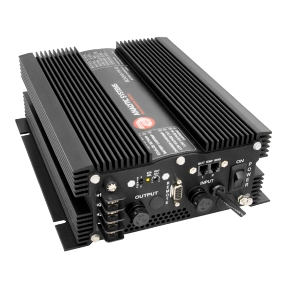
Installation OUTPUT TERMINAL OUTPUT FUSE REMOTE INPUT FUSE INPUT POWER ON/OFF Allow at least 1 inch of clearance all around the case for cooling. The best mounting configu- ration is to mount the unit on a vertical surface oriented as shown. Use #10 screws of the appropriate type for the mounting surface to securely mount the unit. -
Page 8: Operation
To ensure spark free connections the power switch must be in the OFF position prior to making the connections to the battery bank(s). The unit may be hooked to 1, 2 or 3 battery banks. If you are hooking up 2 or 3 battery banks keep in mind that they MUST share a common ground! If you are hooking up 3 battery banks, hook them up as is shown below. - Page 9 recommended for lead-acid batteries. The output adjust potentiometer is located to the right of the 2 stage / 3 stage select switch. If you wish to adjust this voltage, reach in with a very small flat blade screwdriver to rotate the potentiometer. Please Note that this adjusts both the float and absorption voltages at the same time.
-
Page 10: Troubleshooting
Troubleshooting If the red OVERTEMP LED and the audible alarm come on, the unit has overheated, and it will shut down until it cools off sufficiently. You may not have allowed sufficient space around the unit for cooling, or there may be too many devices connected to the output of the unit. Either reduce the number of devices connected to the unit, or reposition the unit for better cooling. -
Page 11: Battery Temperature Sensors
Dry Contact Relay The charger is fitted with a dry contact relay to indicate output failure to a monitoring system. To use the dry contact output fail relay you must connect a 9-pin D connector to the unit. You must use pins one and six as is indicated on the remote connector diagram. The relay is factory preset to fail in the closed position when the low output LED and buzzer come on. -
Page 12: Remote Control Option
Remote Control Option IMPORTANT: This remote is to be used only on Battery Chargers manufactured by Analytic Systems. A remote control panel may be connected to the inverter using a 9-pin D-connector, which attaches to the battery charger. The remote control panel and D connector are part of the remote control option. - Page 13 the battery can be maintained indefinitely. If the battery temperature reaches 120 degrees F (50 degrees C) the equalize cycle will end and the charger output reduced to a very low voltage until the battery cools, and then the charger will return to the float mode. Remote Battery Temperature Sensor Installation The remote battery temperature sensor allows the monitoring of the battery bank so that the charging profile can be adjusted to optimally charge the battery bank depending on the...
- Page 14 Page intentionally left blank...
-
Page 15: Limited Warranty
2 Years from date of manufacture for non-standard or OEM products 1 Year from date of manufacture for encapsulated products. 3. Analytic Systems will determine eligibility for warranty from the date of purchase shown on the warranty card when returned within 30 days, or... - Page 16 An ISO9001 and AS9100 Registered Company Battery Chargers • Inverters • Power Supplies • Voltage Converters 8128 River Way, Delta B.C. V4G 1K5 Canada T. 604.946.9981 F. 604.946.9983 TF. 800.668.3884 (US/CANADA) www.analyticsystems.com...
Need help?
Do you have a question about the BCA310-110-48 and is the answer not in the manual?
Questions and answers