Table of Contents
Advertisement
Quick Links
Advertisement
Table of Contents

Subscribe to Our Youtube Channel
Related Manuals for Analytic Systems BCA610 Series


Summary of Contents for Analytic Systems BCA610 Series
- Page 1 INSTALLATION & OPERATION MANUAL BCA610 SERIES AC SOURCE BATTERY CHARGER...
-
Page 2: Battery Charger Precautions
AC SOURCE BATTERY CHARGER IMPORTANT SAFETY INSTRUCTIONS SAVE THESE INSTRUCTIONS — This manual contains important safety and operating instructions for the battery charger. BATTERY CHARGER PRECAUTIONS Do not expose the battery charger to rain or snow unless it is a sealed model. Use of an attachment not recommended or sold by the battery charger manufacturer may result in a risk of fire, electric shock, or injury to persons. - Page 3 Improper connection can result in the risk of electric shock. Medical Equipment Notice Analytic Systems does not recommend the use of their products in life support applications where failure or malfunction of this product can be reasonably expected to cause failure of the life support device or to significantly affect its safety or effectiveness.
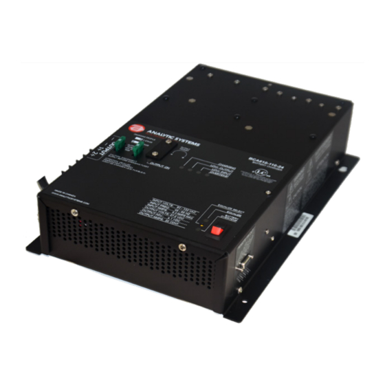
- Page 4 Introduction The BCA610 AC source battery charger provides up to 600 watts of precision charging power to charge your one or two bank battery system. The batteries must share a common ground. This unit can be built to operate from any conventional AC mains power of 110 or 220 VAC .In the absence of a battery, the BCA610 can also function as a power supply up to its continuous current rating.
-
Page 5: Specifications
Marine Grade Aluminum Finish Black Anodize / Black Powder Epoxy Fastenings 18-8 Stainless Weight 7.2 lb / 3.3 kg * Specifications subjects to change without notice. * This is Analytic Systems’ suggested range. Please consult your battery manufacturer for their recommendations. -
Page 6: Installation
Installation Mounting Mount the unit in a DRY and WELL VENTI- LATED location with at least 4 inches of clearance all around it. The ideal mount- ing configuration is to mount the unit flat on a horizontal surface. #10 screws are recommended for attaching the unit to the surface. - Page 7 This unit is equipped with a pair of RJ45 “telephone jack” connectors to serve as connections for up to 2 Analytic Systems battery temperature sensors. If only 1 sensor is being used, it must be plugged into ‘BATT 1” port. This sensor communicates the temperature of the battery to the charger, and is required for the voltage temperature compensation function, over temperature shutdown and user-initiated equalize cycle.
-
Page 8: Operation
Operation The BCA610 is designed for simple and intuitive operation. Before operating, make sure this unit is properly installed and connected. See Installation for more information. To charge a battery Select the type of charging profile using the Stage Select switch on the top panel. See Charging Profiles for more information. -
Page 9: Charging Profiles
Charging Profiles This unit features two user-selectable charging profiles. You can choose which type of charg- ing profile, two stage or three stage, is used to charge your batteries using the Stage Select switch on the front panel. Below are explanations of the two profiles: Two Stage Charging Bulk Float... -
Page 10: Troubleshooting
Troubleshooting This unit is fitted with LED indicators and an alarm buzzer to display and diagnose any problems in operation. In the event of a malfunction, the unit will sound the buzzer to alert you prior to shutting itself down. You should immediately check which LEDs are glowing to determine the cause of the alarm. -
Page 11: Battery Temperature Sensors
Dry Contact Relay To use your dry contact output fail relay you must connect a 9-pin D connector to the unit. You must use pins one and six as is indicated on page 9 in the remote connector diagram. The relay is factory preset to fail in the closed position when the low output LED and buzzer come on. -
Page 12: Remote Control Option
IMPORTANT: This remote is to be used only on Battery Chargers manufactured by Analytic Systems. REMOTE CONNECTOR This connector is located on the side of the unit. Important: To prevent the possibility of High Voltage Electrical Shock, do not power up the battery charger unless all wiring from the unit to the remote is securely connected. - Page 13 the time. If the Charging LED is off when the button is pressed, the Equalize cycle will begin immediately. The charger will charge the battery at approximately 10% its normal rate (i.e. 4 amps for a 40 amp charger) until the battery reaches equalize voltage and then the current reduces as neces- sary to maintain the battery at that voltage.
-
Page 14: Limited Warranty
2 Years from date of manufacture for non-standard or OEM products 1 Year from date of manufacture for encapsulated products. 3. Analytic Systems will determine eligibility for warranty from the date of purchase shown on the warranty card when returned within 30 days, or...
Need help?
Do you have a question about the BCA610 Series and is the answer not in the manual?
Questions and answers