Table of Contents
Advertisement
Quick Links
Advertisement
Table of Contents

Subscribe to Our Youtube Channel
Related Manuals for Analytic Systems BCA310MS


Summary of Contents for Analytic Systems BCA310MS
- Page 1 INSTALLATION & OPERATION MANUAL BCA310MS Battery Charger An ISO9001 and AS9100 Registered Company Battery Chargers • Inverters • Power Supplies • Voltage Converters 8128 River Way, Delta B.C. V4G 1K5 Canada T. 604.946.9981 F. 604.946.9983 TF. 800.668.3884 (US/CANADA) www.analyticsystems.com...
- Page 2 Copyright (2005-2014) Analytic Systems Ware (1993) Ltd.
-
Page 3: Important & Safety Instructions
IMPORTANT & SAFETY INSTRUCTIONS SAVE THESE INSTRUCTIONS — This manual contains important safety and operating instruc- tions for the battery charger. ALL BATTERY CHARGERS 1. CAUTION — To reduce risk of injury, charge only lead acid or sealed gel cell type rechargeable batteries. - Page 4 Analytic Systems does not recommend the use of any of its products in direct patient care.
- Page 5 Examples of devices considered to be life support devices are neonatal oxygen analyzers, nerve stimulators (whether used for anesthesia, pain relief, or other purposes), autotransfu- sion devices, blood pumps, defibrillators, arrhythmia detectors and alarms, pacemakers, hemodialysis systems, peritoneal dialysis systems, neonatal ventilator incubators, ventilators for both adults and infants, anesthesia ventilators, and infusion pumps as well as any other devices designated as “critical”...
-
Page 6: Specifications
Marine Grade Aluminum Finish Black Powder Epoxy Fastenings 18-8 Stainless Weight 7.0 lb / 3.2 kg Safety ABS 11-HS794404A-PDA * Specifications subject to change without notice. * This is Analytic Systems’ suggested range. Please consult your battery manufacturer for their recommendations. -
Page 7: Installation
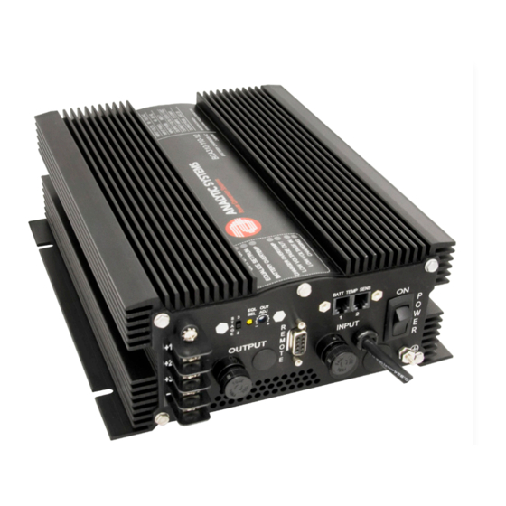
Designed and manufactured by: ANALYTIC SYSTEMS WARE (1993) LTD. 8128 River Way p. 604.946.9981 f. 604.946.9983 Delta, BC V4G 1K5 Canada tf. 800.668.3884 US/Canada www.analyticsystems.com analyticinfo@analyticsystems.com Revised July 2014 Installation OUTPUT TERMINAL OUTPUT FUSE REMOTE INPUT FUSE INPUT POWER ON/OFF Allow at least 1 inch of clearance all around the case for cooling. -
Page 8: Operation
To ensure spark free connections the power switch must be in the OFF position prior to making the connections to the battery bank(s). The unit may be hooked to 1, 2 or 3 battery banks. If you are hooking up 2 or 3 battery banks keep in mind that they MUST share a common ground! If you are hooking up 3 battery banks, hook them up as is shown below. - Page 9 A two-stage charger is preferred for “loaded” batteries and a three-stage for idle or unloaded batteries during recharging. All of Analytic Systems’ chargers include adjustable output voltage for charging standard or deep cycle lead-acid, VLRA or gel type batteries.
-
Page 10: Troubleshooting
Troubleshooting If the red OVERTEMP LED and the audible alarm come on, the unit has overheated, and it will shut down until it cools off sufficiently. You may not have allowed sufficient space around the unit for cooling, or there may be too many devices connected to the output of the unit. Either reduce the number of devices connected to the unit, or reposition the unit for better cooling. -
Page 11: Battery Temperature Sensors
Dry Contact Relay The charger is fitted with a dry contact relay to indicate output failure to a monitoring system. To use the dry contact output fail relay you must connect a 9-pin D connector to the unit. You must use pins one and six as is indicated on the remote connector diagram. The relay is factory preset to fail in the closed position when the low output LED and buzzer come on. -
Page 12: Remote Control Option
IMPORTANT: This remote is to be used only on Battery Chargers manufactured by Analytic Systems. REMOTE CONNECTOR This connector is located on the side of the unit. Important: To prevent the possibility of High Voltage Electrical Shock, do not power up the battery charger unless all wiring from the unit to the remote is securely connected. - Page 13 The charger will charge the battery at approximately 10% its normal rate (i.e. 4 amps for a 40 amp charger) until the battery reaches a maximum voltage of 15.5 volts (31.0 volts for a 24V battery, etc.) and then reduce the current as necessary to maintain the battery at that voltage. Three hours after the Equalize cycle begins, the charger will return to the float mode where the battery can be maintained indefinitely.
- Page 14 Special Services & Options Conformal Coating INCLUDED ON ALL UNITS UNLESS REQUESTED NOT TO as of April 1, 2014 Option “c” Ruggedization Package (EXTRA Conformal Coating and RTV Compound) Option “v” Marine / Industrial Pkg (EXTRA Conformal dipping and RTV Compound) Option “MS”...
-
Page 15: Limited Warranty
2 Years from date of manufacture for non-standard or OEM products 1 Year from date of manufacture for encapsulated products. 3. Analytic Systems will determine eligibility for warranty from the date of purchase shown on the warranty card when returned within 30 days, or... - Page 16 An ISO9001 and AS9100 Registered Company Battery Chargers • Inverters • Power Supplies • Voltage Converters 8128 River Way, Delta B.C. V4G 1K5 Canada T. 604.946.9981 F. 604.946.9983 TF. 800.668.3884 (US/CANADA) www.analyticsystems.com...
Need help?
Do you have a question about the BCA310MS and is the answer not in the manual?
Questions and answers