Table of Contents
Advertisement
Quick Links
CC-Link/LT Remote I/O Module
Thank you very much for purchasing this product.
Please read this manual thoroughly before starting to use the product
and handle the product properly.
2003 MITSUBISHI ELECTRIC CORPORATION
CL2XY16-DTP1C5V
User's Manual
MODEL CL2XY16-DTP1C5V-U
MODEL
CODE
IB(NA)-0800260-A(0308)MEE
(Hardware)
13JP27
Advertisement
Table of Contents

Related Manuals for Mitsubishi CL2XY16-DTP1C5V


Summary of Contents for Mitsubishi CL2XY16-DTP1C5V
- Page 1 CC-Link/LT Remote I/O Module User's Manual (Hardware) Thank you very much for purchasing this product. Please read this manual thoroughly before starting to use the product and handle the product properly. MODEL CL2XY16-DTP1C5V-U MODEL 13JP27 CODE IB(NA)-0800260-A(0308)MEE 2003 MITSUBISHI ELECTRIC CORPORATION...
- Page 2 Also pay careful attention to safety and handle the module properly. These precautions apply only to Mitsubishi equipment. Refer to the user's manual of the CPU module to use for a description of the PLC system safety precautions.
- Page 3 [INSTALLATION PRECAUTIONS] CAUTION Use the module in an environment that meets the general specifications contained in this manual. Using this module in an environment outside the range of the general specifications could result in electric shock, fire, erroneous operation, and damage to or deterioration of the product. Do not directly touch the module's conductive parts.
- Page 4 This manual confers no industrial property rights or any rights of any other kind, nor does it confer any patent licenses. Mitsubishi electric Corporation cannot be held responsible for any problems involving industrial property rights which may occur as a result of using the contents noted in this manual.
-
Page 5: Table Of Contents
CONTENTS 1. Overview ......................1 2. Specifications....................1 2.1 General Specifications................1 2.2 Performance specifications...............2 3. Part Names ....................3 4. Handling Precautions ..................5 5. Wiring......................6 5.1 External wiring ..................6 5.2 Connection and wiring of the connector for I/O interface......7 6. External Dimensions ..................8... -
Page 6: Overview
1. Overview This user's manual explains specifications and names of individual parts of the CL2XY16-DTP1C5V type CC-Link/LT remote I/O module (hereinafter abbreviated as remote I/O module). 2. Specifications 2.1 General Specifications The General specifications for the remote I/O module are shown in the following table. -
Page 7: Performance Specifications
2.2 Performance specifications The performance specifications for the remote I/O module are shown in the following table. Type CL2XY16-DTP1C5V Item Input specifications Output specifications Number of inputs 8 points Number of outputs 8 points Isolation method Photocoupler isolation Isolation method... -
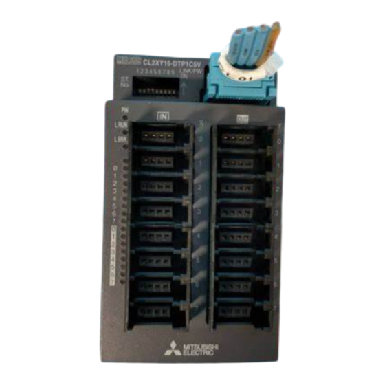
Page 8: Part Names
3. Part Names This section explains the names of the components for the remote I/O module. CL2XY16-DTP1C5V 1 2 3 4 5 6 7 8 LINK/PW L RUN L ERR. Signal Signal Signal Signal Connector for I/O interface Pin No. - Page 9 Item Description Operating LED name Confirmation details status indicator On: Power supply on. LEDs Off: The power supply is turned off or the voltage drop is too large. On: Normal communication. L RUN Off : Communication cutoff (time expiration error). On: Indicates that a communication data error has occurred or the setting switch is outside the allowable range.
-
Page 10: Handling Precautions
4. Handling Precautions (1) When using a DIN rail, attach the DIN rail after taking the following items into consideration: (a) Applicable DIN rail types (conform to JIS C 2812) TH35-7.5Fe TH35-7.5Al (b) Interval between the DIN rail's installation screws Tighten the screws using a pitch of 200mm (7.87in.) or less when attaching a DIN rail. -
Page 11: Wiring
5. Wiring 5.1 External wiring Connector for CL2XY16-DTP1C5V CC-Link/LT Insulation interface +24V DC/DC Connector for I/O interface CON1 +24V 3-wire sensor (Sink output) (NPN output type) Direction CON2 circuit +24V 2-wire sensor Direction (Sink output) circuit CON8 +24V (Sink output) -
Page 12: Connection And Wiring Of The Connector For I/O Interface
5.2 Connection and wiring of the connector for I/O interface Wire the connector for I/O Interface according to the following procedure: (1) Verify that the plug cover is installed in the plug unit. Caution: Do not push the plug cover into the plug unit before the cable is inserted. -
Page 13: External Dimensions
6. External Dimensions 39 (1.54) 48 (1.89) CL2XY16-DTP1C5V LINK/PW L RUN L ERR. Center of DIN rail (0.16) Unit: mm (inch) - Page 14 Warranty Mitsubishi will not be held liable for damage caused by factors found not to be the cause of Mitsubishi; machine damage or lost profits caused by faults in the Mitsubishi products; damage, secondary damage, accident compensation caused by special factors unpredictable by Mitsubishi;...
Need help?
Do you have a question about the CL2XY16-DTP1C5V and is the answer not in the manual?
Questions and answers