Advertisement
Quick Links
FX
-2DA SPECIAL FUNCTIONBLOCK
2N
This manual contains text, diagrams and explanations which will guide the reader in the correct installation
and operation of the FX
-2DA special function block and should be read and understood before
2N
attempting to install or use the unit.
Further information can be found in the FX SERIES PROGRAMMING MANUAL(ΙΙ), FX
FX
SERIES HARDWARE MANUAL of each PLC.
2NC
1. INTRODUCTION
The FX
-2DA type analog output block (hereafter referred to as the FX
2N
digital value of 12 bits into an analog output of two points (voltage and current output), and to forward the
values to the Programmable Controller (hereafter referred to as a PLC).
FX
-2DA can connected to the FX
, FX
, FX
, and the FX
2N
0N
1N
2N
1) The analog output is selected from the voltage or current output by the method of connecting wires.
At this time, assume setting to be two channels common analog output.
2) The two analog output channels can accept outputs of 0 to 10V DC, 0 to 5V DC, or 4 to 20mA.
(A mixture of voltage/current output is possible.)
3) Resolution is 2.5mV (0 to 10V DC) and 4µA(4 to 20mA).
4) The digital to analog conversion characteristics can be adjusted.
5) The block occupies 8 I/O points which can be allocated from either the inputs or outputs.
6) The data transfer with the PLC uses the FROM/TO instructions.
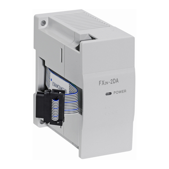
2. EXTERNAL DIMENSIONS AND PARTS
E x t e n s i o n
c a b l e
D I N r a i l
m o u n t i n g
s l o t
F X
- 2 D A
2 N
3 5 m m ( 1 . 3 8 )
P O W E R
M o u n t i n g
h o l e s
2 h o l e s 4 . 5
( 0 . 1 8 ) d i a
9 ( 0 . 3 5 )
4 ( 0 . 1 6 )
8 7 ( 3 . 4 3 )
4 3 ( 1 . 6 9 )
Mass (Weight):0.2kg (0.44lbs)
Accessories: Special Function block number label
3. WIRING
+15V
DC/DC
AG
PLC
converter
-15V
Extension
cable
FX
-2DA
2N
*1 Connect a 0.1 to 0.47 µF 25V DC capacitor respective to position *1 when there is voltage
ripple in the voltage output or there is a lot of noise.
*2 For voltage output please short circuit IOUT and COM as shown in the diagram.
*3 Channel number enter
.
4. CONNECTION WITH PROGRAMMABLE CONTROLLER
1) The FX
-2DA and main unit are connected by a cable on the right of the main unit.
2N
2) Up to 4 FX
4 for the FX
However the following limitation exists when the undermentioned special function blocks are connected.
USER'S GUIDE
FX
:
Main unit and powered extension units of 32 points I/O or less. Consumption current available
2N
for undermentioned special function blocks ≤ 190mA
JY992D74901D
FX
:
Main unit and powered extension units of I/O 48 points or more. Consumption current available
2N
for undermentioned special function blocks ≤ 300mA
FX
:
Up to 4 undermentioned special function blocks can be connected regardless of the system I/O.
2NC
FX
: Main unit and powered extension units. Up to 2 undermentioned special function blocks can be
0N/1N
connected regardless of the system I/O.
/FX
/FX
/
0N
1N
2N
Consumption current of 24V DC for one unit
The consumption of the above units is to be subtracted from the service power supply of the host
PLC.
3) The blocks occupies 8 I/O points (the 8 points can be allocated from either inputs or outputs).
4) FX
-2DA consumes 5V DC 30mA.
2N
-2DA) is used to convert a
2N
The total 5V consumption of all special function blocks connected to either an FX
or an FX
2N
series Programmable Controllers.
2NC
5. SPECIFICATIONS
5.1 Environmental specification
Item
Directric Withstand
voltage
Environmental specifications other than the above are the same as the main unit of the
Programmable Controller. (Refer to the Hardware manual of the Programmable controller)
5.2 Power supply specification and others
Item
Analog circuits
Digital circuits
Dimensions: mm (inches)
M 3 ( 0 . 1 2 )
Isolation
t e r m i n a l s c r e w s
Number of occupied
I/O points
C H 1
O F F S E T
5.3 Defining gain and offset
P O W E R
Item
C H 1
G A I N
C H 2
O F F S E T
C H 2
G A I N
C H 1
O F F S E T
P O W E R
Range of analog output
C H 1
G A I N
C H 2
O F F S E T
C H 2
G A I N
O F F S E T / G A I N
v o l u m e
Digital input
Resolution
Voltage output
Integrated accuracy
VOUT
Inverter
*1
Processing time
etc
IOUT
COM
*2
Current output
VOUT
IOUT
Recorder
etc
COM
*3
Output characteristics
-2DA units can connect to the FX
series PLC, up to 5 for FX
2N
0N
series PLC, all with powered extension units.
2NC
FX
-2DA
FX
-2AD
2N
2N
85mA
50mA
extension unit must not exceed the 5V source capacity of the system.
Content
500V AC 1min (between analog output terminals and case)
Content
24V DC ±10% 85mA (Internal power supplied from the main unit)
5V DC 30mA (Internal power supplied from the main unit)
Photo-coupler isolation between analog and digital circuits.
(No isolation between analog channels.)
The blocks occupies either 8 input or output points.
(Can be either inputs or outputs)
Voltage output
Current output
At shipping, the unit is adjusted to a digital range of 0 to 4000 for an analog
voltage output of 0 to 10V DC. When using an FX
2N
differing voltage output except 0 to 10V DC, it is necessary to adjust the
offset and gain.
0 to 10V DC, 0 to 5V DC
4 to 20mA
(External load resistance 2K to
(External load resistance 400Ω or
1MΩ)
less)
12bit
2.5mV: 10V/4000(At shipment)
4µA: (20-4)A/4000
Change depending on the output
Change depending on the output
characteristic.
characteristic.
± 0.1V
± 0.16mA
4ms/1 channel (synchronized to be sequence program)
Analog value
:0 to 10V
at
Analog value
Digital value
:0 to 4000
shipment
Digital value
10.238V
10V
20mA
4mA
0
4000
Digital value
If a digital source data of greater than 12 bits is used, only the lower 12 bits
will be valid. Additional (upper) bits will be ignored
Use a digital value within the range from 0 to 4095.
The output characteristic can be set to each of the two channels.
6. ALLOCATION OF BUFFER MEMORY (BFM)
6.1 Buffer memory
up to 8 for FX
or, up to
1N,
2N
BFM
b15 to b8
number
#0 to #15
#16
Reserved
#17
Reserved
#18 or more
BFM#16: The D/A conversion data of the channel specified with BFM#17 (digital value) is written.
FX
-3A
0N
The D/A data is written in binary in order of the lower 8bit and higher 4bit and divided into two
portions.
90mA
BFM#17: b0•••The D/A conversion of CH2 begins by changing of 1→0.
b1•••The D/A conversion of CH1 begins by changing of 1→0.
b2•••The lower eight bit data for the D/A conversion is held by changing of 1→0.
Write data in the above-mentioned buffer memory by "8. Program example".
, FX
main unit
2N
2NC
-2DA for current or
:4 to 20mA
:0 to 4000
20.380mA
0
4000
Digital value
b7 to b3
b2
b1
b0
Reserved
Digital source data for output (8 bit)
CH1 D/A
CH2 D/A
Lower data holding
conversion
conversion
bit
beginning
beginning
Reserved
Advertisement

Related Manuals for Mitsubishi FX2N-2DA


Summary of Contents for Mitsubishi FX2N-2DA
- Page 1 4. CONNECTION WITH PROGRAMMABLE CONTROLLER 6. ALLOCATION OF BUFFER MEMORY (BFM) 1) The FX -2DA and main unit are connected by a cable on the right of the main unit. 6.1 Buffer memory 2) Up to 4 FX -2DA units can connect to the FX series PLC, up to 5 for FX up to 8 for FX or, up to...
- Page 2 [T 0 K 17 H 0002 the FX -2DA. • Under no circumstances will Mitsubishi Electric be liable or responsible for any consequential [T 0 K 17 H 0000 Voltage output V oltage output V oltage output e )The D/A conversion of CH1 is damage that may arise as a result of the installation or use of this equipment.
Need help?
Do you have a question about the FX2N-2DA and is the answer not in the manual?
Questions and answers