Advertisement
This manual contains text, diagrams and explanations which will guide the reader in the correct installation
and operation of the FX TERMINAL BLOCKS. It should be read and understood before attempting to
install or use the unit. Further information can be found in the FX series PLC hardware manuals.
If in doubt at any stage during the installation of the FX TERMINAL BLOCKS always consult a profes-
sional electrical engineer who is qualified and trained to the local and national standards.
All terminal blocks described in this manual conform to the UL/cUL Standard.
Note's on the symbology used in this manual
At various times through out this manual certain symbols will be used to highlight points of infor-
mation which are intended to ensure the users personal safety and protect the integrity of the
equipment. Whenever any of the following symbols are encountered, its associated note must be
read and understood. Each of the symbols used will now be listed with a brief description of its
meaning.
Hardware warnings
1) Indicates that the identified danger WILL cause physical and property damage.
2) Indicates that the identified danger could POSSIBLY cause physical and property damage.
Guidelines for the safety of the user and protection of the FX TERMINAL BLOCKS
•
This manual has been written to be used by trained and competent personnel. This is defined
by the European directives for machinery, low voltage and EMC.
•
If in doubt at any stage during the installation of the FX TERMINAL BLOCKS always consult a
professional electrical engineer who is qualified and trained to the local and national stan-
dards. If in doubt about the operation or use of the FX TERMINAL BLOCKS please consult
the nearest Mitsubishi Electric distributor.
•
Under no circumstances will Mitsubishi Electric be liable or responsible for any consequential
damage that may arise as a result of the installation or use of this equipment.
•
All examples and diagrams shown in this manual are intended only as an aid to understand-
ing the text, not to guarantee operation. Mitsubishi Electric will accept no responsibility for
actual use of the product based on these illustrative examples.
•
Owing to the very great variety in possible application of this equipment, you must satisfy
yourself as to its suitability for your specific application.
1. INTRODUCTION
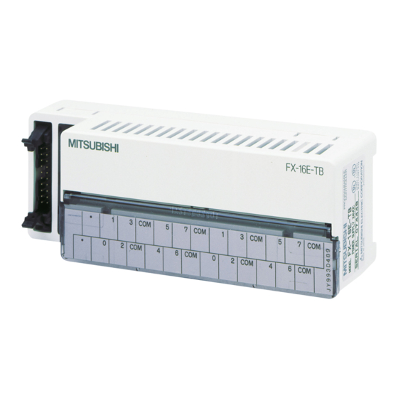
Terminal blocks convert I/O terminals of connector type PLC into terminal blocks. Some terminal blocks
directly extend inputs and outputs of PLC. Other terminal blocks are equipped with diversified built-in
devices, and function only as inputs or only as outputs.
MODEL
FX-16E-TB/UL
FX-32E-TB/UL
FX-16EYR-ES-TB/UL
FX-16EYS-ES-TB/UL
FX-16EYT-ESS-TB/UL
FX-16EYT-ES-TB/UL
FX-16EX-A1-TB/UL
FX INPUT AND OUTPUT TERMINAL BLOCKS
INPUT
16 pt (Direct input/output)
32 pt or 16/16 pt (Direct input/output)
16 pt (Relay)
16 pt (Triac)
16 pt
(Transistor source)
16 pt
(Transistor sink)
16 pt (100V AC)
USER'S GUIDE
JY992D50401F
OUTPUT
APPLICABLE PLC
FX
-ooMT-ESS/UL
2C
FX
2NC
FX
2NC
FX
2NC
FX
-ooMT-E/UL
2C
FX
-ooMT-ESS/UL
2C
FX
2NC
FX
2NC
FX
-ooMT-E/UL
2C
CURRENT
CONSUMPTION
-ooMT-DSS
-ooEX-DS
-ooEYT-DSS
80mA (5mA/1pt)
-ooMT-DSS
112mA (7mA/1pt)
-ooEYT-DSS
48mA (3mA/1pt)
Advertisement
Table of Contents

Related Manuals for Mitsubishi FX-16E-TB/UL


Summary of Contents for Mitsubishi FX-16E-TB/UL
- Page 1 All examples and diagrams shown in this manual are intended only as an aid to understand- ing the text, not to guarantee operation. Mitsubishi Electric will accept no responsibility for actual use of the product based on these illustrative examples.
- Page 2 FX-16EX-A1-TB 16 pt (100V AC) 48mA (3mA/1pt) -ooEX-D/UL 2. EXTERNAL DIMENSION FX-16E-TB/UL, FX-16E-TB FX-32E-TB/UL FX-16EYo o o o (o o o o : R/T/S)-TB/UL FX-32E-TB FX-16EYo o o o (o o o o : R/T)-TB FX-16EX-A1-TB/UL, FX-16EX-A1-TB Unit: mm(inches) 150(5.91)
- Page 3 5. TERMINAL WIRING Never perform external wiring to unused terminals . Such wiring may damage the unit. Note Do not lay I/O cables next to power cables or allow them to share the same trunking duct. For M3.5 Where I/O signals are used over an extended distance consideration (0.14in) must be made for voltage drop and noise interference.
- Page 4 n n n n Outputs TYPICAL WIRING TYPE PLC Outputs -ooMT-ESS/UL -ooMT-DSS Source -ooEYT-DSS Fuse Lamp PLC Outputs -ooMT-E/UL -ooMT-D/UL Sink -ooEYT-D/UL Fuse Lamp For the I/O specifications and detailed information, refer to the FX Hardware Manual or the FX Hard- ware Manual.
- Page 5 n n n n Relay output blocks FX-16EYR-ES-TB/UL, FX-16EYR-TB wiring 1 2 3 5 6 7 && 1 2 3 && 4 5 6 7 OUTPUT No. Power supply for relays +10% 24V DC -15% Terminal blocks are not equipped with built-in fuses. In order to prevent breakdown of circuits caused by load short-circuit, provide a fuse of 5 to 10 A for every four points.
- Page 6 Manual number : JY992D50401 Manual revision : F Date : JUL. 2001 HEAD OFFICE : MITSUBISHI DENKI BLDG MARUNOUTI TOKYO 100-8310 TELEX : J24532 CABLE MELCO TOKYO HIMEJI WORKS : 840, CHIYODA CHO, HIMEJI, JAPAN Effective JUL. 2001 JY992D50401F...
- Page 7 • All examples and diagrams shown in this manual are intended only as an aid to understand- Terminal blocks ing the text, not to guarantee operation. Mitsubishi Electric will accept no responsibility for FX-16E-TB PLC Inputs actual use of the product based on these illustrative examples.
- Page 8 Indicator input supply 24V DC 5mA/1pt 24V DC 7mA/1pt 24V DC 7mA/1pt Output HEAD OFFICE : MITSUBISHI DENKI BLDG MARUNOUTI TOKYO 100-8310 TELEX : J24532 CABLE MELCO TOKYO absorber HIMEJI WORKS : 840, CHIYODA CHO, HIMEJI, JAPAN Effective JUL. 2001...
Need help?
Do you have a question about the FX-16E-TB/UL and is the answer not in the manual?
Questions and answers