
Related Manuals for Mitsubishi AJ65BT-64RD3


Summary of Contents for Mitsubishi AJ65BT-64RD3
- Page 1 Pt 100 Temperature Input Module Type AJ65BT-64RD3/AJ65BT-64RD4 User s Manual Mitsubishi Programmable Controller...
- Page 2 www.plcworld.cn...
- Page 3 Also pay careful attention to safety and handle the module properly. These precautions apply only to Mitsubishi equipment. Refer to the user's manual of the used CPU module for a description of the PLC system safety precautions.
- Page 4 www.plcworld.cn [INSTALLATION PRECAUTIONS] CAUTION The module should be used under the environmental conditions listed under the general specifications in the manual. Using it under any other environmental conditions could cause problems such as fire, malfunction and damage to or deterioration of the product. The module should be fixed securely with a DIN rail or installation screws, and then make sure to tighten it within the range of the specified torque of the installation screws.
- Page 5 www.plcworld.cn [WIRING PRECAUTIONS] CAUTION Be sure that the wires or cables connected to the module are stored in the duct or fixed with cramps. Failure to do so may cause a damage to the module or cables due to dangling, shifting or inadvertent handling of calbes, or malfunction due to bad cable contacts.
- Page 6 www.plcworld.cn [DISPOSAL PRECAUTION] CAUTION When disposing of this product, treat it as industrial waste.
- Page 7 Japanese Manual Version SH-3652-F This manual does not imply guarantee or implementation right for industrial ownership or implementation of other rights. Mitsubishi Electric Corporation is not responsible for industrial ownership problems caused by use of the contents of this manual.
-
Page 8: Table Of Contents
Introduction Thank you for purchasing the Mitsubishi Graphic Operation Terminal. Before using the equipment, please read this manual carefully to develop full familiarity with the functions and performance of the graphic operation terminal you have purchased, so as to ensure correct use. - Page 9 4.7.1 Handling precautions for CC-Link dedicated cable................4-10 4.7.2 Wiring example with CC-Link modules ....................4-10 4.7.3 Precautions when wiring to a platinum temperature-measuring resistor ..........4-11 4.7.4 Connecting AJ65BT-64RD3 and platinum temperature-measuring resistor.......... 4-11 4.7.5 Connecting AJ65BT-64RD and platinum temperature-measuring resistor..........4-12 PROGRAMMING 5-1 to 5-15 Programming Procedure...........................
- Page 10 Conformation to the EMC Directive and Low Voltage Instruction When complying with EMC Directives and Low-Voltage Directives by assembling a Mitsubishi PLC compatible with EMC Directive and Low-Voltage Directives into the user product, refer to Chapter 3 "EMC Directives and Low-Voltage Directives" in the User’s Manual (Hardware) for the CPU module being used.
- Page 11 About Generic Terms and Abbreviations Unless otherwise specified, this manual uses the following generic terms and abbreviations to explain the AJ65BT-64RD3/AJ65BT-64RD4 platinum temperature-measuring resistor Pt100 temperature input module. Generic Term/ Description Abbreviation GX Developer Generic product name for product model names SWnD5C-GPPW, SWnD5C-GPPW-A, SWnD5C-GPPW-V and SWnD5C-GPPW-VA.
- Page 12 Packing List This product consists of the following items. Product name Quantity AJ65BT-64RD3 platinum temperature-measuring resistor Pt100 temperature input module AJ65BT-64RD4 platinum temperature-measuring resistor Pt100 temperature input module AJ65BT-64RD3/AJ65BT-64RD4 platinum temperature-measuring resistor Pt100 temperature input module user's manual (hardware)
- Page 13 www.plcworld.cn MEMO...
-
Page 14: Overview
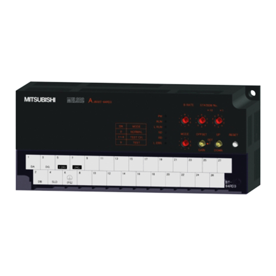
Control & Communication Link (abbreviated as CC-Link from here on) system. The AJ65BT-64RD3 is a 3-wire system connecting module for the platinum temperature-measuring resistor. The AJ65BT-64RD4 is a 4-wire system connecting module for the platinum temperature-measuring resistor. -
Page 15: System Configuration
www.plcworld.cn 2. SYSTEM CONFIGURATION MELSEC-A SYSTEM CONFIGURATION System configuration when using the AJ65BT-64RD is explained below. Overall Configuration The overall configuration when using the AJ65BT-64RD is shown below. Master/local module for CC-Link (master station) Master/local module for CC-Link (local station) CC-Link dedicated cable (Intelligent device station) (Remote I/O station) -
Page 16: Applicable Systems
The module where "9707 B" is not indicated in the DATE column cannot be used. <Large type> <Small type> MITSUBISHI CPU UNIT PROGRAMMABLE CONTROLLER MODEL DATE 9707 DATE 9707 MITSUBISHI ELECTRIC CORPORATION JAPAN BD992D008H40 MITSUBISHI ELECTRIC BD992D008H40 Date of Function Date of Function manufacture version manufacture... -
Page 17: Specifications
www.plcworld.cn 3. SPECIFICATIONS MELSEC-A SPECIFICATIONS This section explains the AJ65BT-64RD the general specifications, performance specifications, and transmission specifications. General Specification This section explains the AJ65BT-64RD general specifications. Table 3.1 General Specification Item Specifications Ambient operating 0 to 55 ° temperature Ambient storage temperature -20 to 75 °... -
Page 18: Performance Specification
3. SPECIFICATIONS MELSEC-A Performance Specification The performance specification of the AJ65BT-64RD is explained below. Item AJ65BT-64RD3 AJ65BT-64RD4 Measurement method 3-wire 4-wire Connectable platinum temperature- Pt 100, JPt 100 measuring resistor 1 mA Output current for detecting temperature Temperature input range –180 to 600 °C... -
Page 19: Specifications When Connecting To A Platinum Temperature-Measuring Resistor
3. SPECIFICATIONS MELSEC-A Performance specification (continued) Item AJ65BT-64RD3 AJ65BT-64RD4 External power supply 24 V DC (18 to 30 V DC) Internal consumed current 0.17 A Allowable momentary power failure period Weight 0.38 (0.84) kg (lb.) *1 : Conversion speed is the time until it is converted to the corresponding digital value after the temperature has been input, and then stored in the remote register. -
Page 20: Data Link Processing Time
www.plcworld.cn 3. SPECIFICATIONS MELSEC-A 3.2.2 Data link processing time For the AJ65BT-64RD, the data link processing time shown below will be required in order to execute each function. For details of the link scan time, refer to the user's manual (details) of the used mater module. Example) Data link processing time in asynchronous mode when the master module is the QJ61BT11 (normal value) (1) Mater station (RY) →... -
Page 21: Function
www.plcworld.cn 3. SPECIFICATIONS MELSEC-A Function The function of AJ65BT-64RD is explained below. 3.3.1 Function list Below is a function list of the AJ65BT-64RD. Item Description Reference section • Performs conversion enable/disable settings by channel. Conversion enable/disable (Default ······ All channels disabled) Section 3.3.2 designation •... -
Page 22: Conversion Enable/Disable Designation
www.plcworld.cn 3. SPECIFICATIONS MELSEC-A 3.3.2 Conversion enable/disable designation Conversion may be enabled or disabled for each channel individually. The setting of the conversion is made through the CH. conversion enable flags (RYn0 to RYn3). Setting Description Wire breakage detection is conducted at the same time the temperature of the target object is taken. Neither temperature detection nor wire breakage detection is conducted. -
Page 23: Sampling Processing/Travel Average Processing Designation
www.plcworld.cn 3. SPECIFICATIONS MELSEC-A 3.3.3 Sampling processing/travel average processing designation The AJ65BT-64RD may designate sampling processing or travel average processing for each individual channel. The setting of sampling processing or travel average processing is made through the CH. sampling processing/travel average processing designation flags (RYn4 to RYn7). Setting Description Travel average processing... - Page 24 www.plcworld.cn 3. SPECIFICATIONS MELSEC-A (2) Sampling processing Stores the detected temperature value and scaling value are stored in the remote register by each sampling time. Sampling time Remote register [°C] 1st storage Detected 2nd storage temperature value 3rd storage Time [ms] The data transition inside the remote register 1st storage 2nd storage...
-
Page 25: Wire Breakage Detection
www.plcworld.cn 3. SPECIFICATIONS MELSEC-A 3.3.4 Wire breakage detection The AJ65BT-64RD detects wire breakage in the platinum temperature-measuring resistor or cable used for each channel, and turns on the wire breakage detection flag (RXn4 to RXn7) for the corresponding channel. On the AJ65BT-64RD, the wire breakage detection are performed for channels that are enabled for conversion. -
Page 26: Detected Temperature
www.plcworld.cn 3. SPECIFICATIONS MELSEC-A 3.3.5 Detected temperature Temperatures in the range of -180 °C to +600 °C can be detected using the AJ65BT-64RD. Of the temperature detected, the values to the first place and third place below decimal point are stored in the remote register (Refer to Section 4.7). -
Page 27: I/O Signals In Respect To The Master Module
www.plcworld.cn 3. SPECIFICATIONS MELSEC-A I/O Signals in Respect to the Master Module The assignment of remote I/O signals and the functions is explained. 3.4.1 Remote I/O signal list The AJ65BT-64RD uses 128 points for input and 128 points for output in respect to the data for the master module. -
Page 28: I/O Signal Functions
www.plcworld.cn 3. SPECIFICATIONS MELSEC-A 3.4.2 I/O signal functions The function of each remote I/O signal for the AJ65BT-64RD is explained below. (1) Remote Input signal Device No. Signal name Description The conversion completion flag turns on when the detected temperature value at all conversion enabled channel is stored in the remote register after power on or a hardware reset. - Page 29 www.plcworld.cn 3. SPECIFICATIONS MELSEC-A (2) Remote output signal Device No. Signal name Description It is possible to designate the conversion enabled or disabled for each channel. By disabling the conversion at channels not in use, generation of unnecessary wire breakage detection flags may be prevented and sampling time may be reduced. ON : Conversion enabled ..
-
Page 30: Remote Register
www.plcworld.cn 3. SPECIFICATIONS MELSEC-A Remote Register The AJ65BT-64RD is equipped with remote registers for data communication with the master module. The assignment and data structure of the remote register are explained below. 3.5.1 Remote register assignment The remote register assignments are shown in the table below. Communicati Reference Address... -
Page 31: Remote Register For Storing Detected Temperature (Address: Rwrn To Rwrn+11)
www.plcworld.cn 3. SPECIFICATIONS MELSEC-A 3.5.2 Remote register for storing detected temperature (Address : RWrn to RWrn+11) AJ65BT-64RD has two types of remote registers, for 16-bit data and 32-bit data, to store the detected temperature values that are converted into digital values. (1) 16-bit data storage (Address : RWrn to RWrn+3) The value to the first place below decimal point of the detected temperature is multiplied by 10, then stored as 16-bit signed binary data. -
Page 32: Setting And Procedure Before Operation
www.plcworld.cn 4. SETTING AND PROCEDURE BEFORE OPERATION MELSEC-A SETTING AND PROCEDURE BEFORE OPERATION The procedure before operation of AG65BT-64RD, part identification and setting, and the wiring method are explained below. Procedure before Operation The procedure before operation of AJ65BT-64RD is explained below. Start Set the switches listed below on AJ65BT-64RD. -
Page 33: Handling Precautions
www.plcworld.cn 4. SETTING AND PROCEDURE BEFORE OPERATION MELSEC-A Handling Precautions The handling precautions for AJ65BT-64RD is explained below. • The module should be fixed securely with a DIN rail or installation screws, and then CAUTION make sure to tighten it within the range of the specified torque of the installation screws. -
Page 34: Part Identification And Setting
4. SETTING AND PROCEDURE BEFORE OPERATION MELSEC-A Part Identification and Setting The part identification and setting method for AJ65BT-64RD is explained below. B RATE STATION NO. MITSUBISHI MELSEC AJ65BT-64RD • • • • • • • • L RUN... - Page 35 L ERR. Flicker at irregular intervals: Indicates that the terminating resistor is not installed or the module or CC-Link dedicated cable is affected by noise. OFF: Normal communication AJ65BT-64RD3 +24V (FG) Terminal block AJ65BT-64RD4 +24V...
-
Page 36: Error Compensation By The Offset Value/Gain Value Setting
www.plcworld.cn 4. SETTING AND PROCEDURE BEFORE OPERATION MELSEC-A Error Compensation by the Offset Value/Gain Value Setting The AJ65BT-64RD error compensation is a function that compensates values at arbitrary 2 points (offset value/gain value) within the usage temperature range at system startup or when a correct temperature cannot be detected. - Page 37 www.plcworld.cn 4. SETTING AND PROCEDURE BEFORE OPERATION MELSEC-A POINT • The offset value/gain value can be obtained with a high accuracy when error compensation is carried out at the minimum and maximum temperatures in the range used. • Set the offset value/gain value while monitoring the detected temperature value, using a peripheral device.
-
Page 38: Initial Settings For Error Compensation
www.plcworld.cn 4. SETTING AND PROCEDURE BEFORE OPERATION MELSEC-A 4.4.1 Initial settings for error compensation The following shows the initial settings using a program designed for executing error compensation. Start Create a program that designates a sampling processing and travel average processing *1 Create a program that reads the detected temperature values *1 Only when executing error compensation with the value detected by travel average processing. -
Page 39: Error Compensation Procedure
www.plcworld.cn 4. SETTING AND PROCEDURE BEFORE OPERATION MELSEC-A 4.4.2 Error compensation procedure The following shows the flow of error compensation. Start Set the mode switch to 9 for test mode. Input a value to be the gain value. Check that RUN LED is turned OFF. AJ65BT-64RD MODE Or, input standard... -
Page 40: Station Number Setting
www.plcworld.cn 4. SETTING AND PROCEDURE BEFORE OPERATION MELSEC-A Station Number Setting The buffer memory addresses of the master module, where the remote I/O signals and read/write data are stored, are determined by the station number setting of the AJ65BT-64RD. For details, refer to the user's manual (details) of the used master module. Orientation of Module Installation The following shows the possible orientation for AJ65BT-64RD installation. -
Page 41: Wiring
www.plcworld.cn 4. SETTING AND PROCEDURE BEFORE OPERATION MELSEC-A Wiring 4.7.1 Handling precautions for CC-Link dedicated cable Avoid following actions when handling CC-Link dedicated cable, since the cables will be damaged. (1) Do not apply pressure to the cable with sharp objects. (2) Do not unduly twist the cable. -
Page 42: Precautions When Wiring To A Platinum Temperature-Measuring Resistor
If they are placed close to each other, the platinum temperature-measuring resistor is influenced more easily by the noise, surge, or conductivity. 4.7.4 Connecting AJ65BT-64RD3 and platinum temperature-measuring resistor (1) The highest accuracy can be obtained if a 3-wire type platinum temperature-measuring resistor is used for AJ65BT-64RD3. -
Page 43: Connecting Aj65Bt-64Rd And Platinum Temperature-Measuring Resistor
www.plcworld.cn 4. SETTING AND PROCEDURE BEFORE OPERATION MELSEC-A 4.7.5 Connecting AJ65BT-64RD and platinum temperature-measuring resistor (1) The highest accuracy can be obtained if a 4-wire type platinum temperature-measuring resistor is used for AJ65BT-64RD4. The following shows a connection example of a 4-wire type platinum temperature-measuring resistor. -
Page 44: Programming
www.plcworld.cn 5. PROGRAMMING MELSEC-A PROGRAMMING The programming procedure, basic programming for read and write, as well as programming examples are explained below. When utilizing the program examples introduced in this chapter for an actual system, fully verify that controllability in the target system has no problems. Refer to the user's manual (details) of the used master module for the master module, to Section 3.5 for the remote registers, and to the AnSHCPU/AnACPU/AnUCPU programming manual (dedicated Instructions) for details of the dedicated instructions. -
Page 45: Program Example Conditions
www.plcworld.cn 5. PROGRAMMING MELSEC-A Program Example Conditions The program examples given in this chapter have been created under the following conditions. (1) System configuration PLC CPU Master station (X0 to X1F/Y0 to Y1F) I/O (Input 64 points) (X20 to X5F) I/O (Output 64 points) (Y60 to Y9F) AJ65BT-64RD (Station No. - Page 46 www.plcworld.cn 5. PROGRAMMING MELSEC-A (2) Relationships between PLC CPU, master module and AJ65BT-64RD AJ65BT-64RD (Station No. 1) PLC CPU Master module Device X Remote input (RX) Remote input (RX) Address X400 to X40F RX00 to RX0F RX00 to RX0F X410 to X41F RX10 to RX1F RX10 to RX1F X420 to X42F...
- Page 47 www.plcworld.cn 5. PROGRAMMING MELSEC-A (3) Initial setting Setting item Description CH. 1 sampling processing/travel average Travel average processing processing designation flag (RY04) CH. 2 sampling processing/travel average Travel average processing processing designation flag (RY05) Offset/gain value selection flag (RY77) Factory setting (4) Other settings Setting item Description...
-
Page 48: Program Examples When Qcpu (Q Mode) Is Used
www.plcworld.cn 5. PROGRAMMING MELSEC-A Program Examples when QCPU (Q Mode) Is Used The network parameters and auto refresh parameters have been set by GX Developer. Initial setting can be made easily by using the remote device station initialization procedure registration function. (1) Parameter setting (a) Network parameter setting (b) Auto refresh parameter setting... - Page 49 www.plcworld.cn 5. PROGRAMMING MELSEC-A (2) Initial setting by remote device station initialization procedure registration function (a) Target station number setting Set the target station number of initial setting. Set the target station number to "1". (b) Procedure registration setting The initial setting is registered to the AJ65BT-64RD when the initial data processing request flag (RX78) turns ON and Remote device station initialization procedure registration (SB0D) is set.
- Page 50 www.plcworld.cn 5. PROGRAMMING MELSEC-A (3) Program example AJ65BT-64RD status check Reads data link status. AJ65BT-64RD data link normal AJ65BT-64RD data link abnormal Initialization procedure registration check Turns ON initialization procedure registration command. Turns OFF initialization procedure registration command. Initial setting change Initial setting change CH.
- Page 51 www.plcworld.cn 5. PROGRAMMING MELSEC-A *1: Correct the program within dotted frame 1) as shown below when remote device station initialization procedure registration is executed for multiple modules. RX(m+1)9 and RX(n+1)9 are initial data setting completion flags. The device numbers change depending on the station number.
-
Page 52: Program Examples When Qnacpu Is Used
www.plcworld.cn 5. PROGRAMMING MELSEC-A Program Examples when QnACPU Is Used The network parameters and auto refresh parameters have been set by GX Developer. (1) Parameter setting (a) Network parameter setting (b) Auto refresh parameter setting... - Page 53 www.plcworld.cn 5. PROGRAMMING MELSEC-A (3) Program example AJ65BT-64RD status check Reads data link status. AJ65BT-64RD data link normal AJ65BT-64RD data link abnormal Initial setting CH. 1 sampling processing/ travel average processing designation flag (RY04) CH. 2 sampling processing /travel average processing designation flag (RY05) Offset/gain value selection flag (RY77)
-
Page 54: Program Example When Acpu/Qcpu (A Mode) Is Used (Dedicated Instructions)
www.plcworld.cn 5. PROGRAMMING MELSEC-A Program Example when ACPU/QCPU (A Mode) Is Used (Dedicated Instructions) The network parameters and auto refresh parameters have been set by the sequence program. (1) Program example Network parameter setting by dedicated instruction RLPA Synchronous mode invalid Number of connected modules: 1 AJ65BT-64RD station... - Page 55 www.plcworld.cn 5. PROGRAMMING MELSEC-A SB head number setting "B" setting B0 setting 512 points setting SW head number setting "W" setting W0 setting 256 points setting Dedicated instruction (RRPA) Master module head I/O No. Parameter storage head device AJ65BT-64RD status check Reads data link status.
- Page 56 www.plcworld.cn 5. PROGRAMMING MELSEC-A Conversion enable/disable designation CH. 1 conversion enable Turns ON CH. 1 conversion enable flag (RY00). CH. 2 conversion enable C H . 2• Ï Š · ‹ – ‰ Â Turns ON CH. 2 conversion enable flag (RY01). Detected temperature value read Reads CH.
-
Page 57: Program Example When Acpu/Qcpu (A Mode) Is Used (From/To Instructions)
www.plcworld.cn 5. PROGRAMMING MELSEC-A Program Example when ACPU/QCPU (A Mode) Is Used (FROM/TO Instructions) The network parameters have been set by the sequence program. (1) Program example Network parameter setting Number of connected modules: 1 Number of retries: 3 Number of automatic return modules: 1 Writes to master station. - Page 58 www.plcworld.cn 5. PROGRAMMING MELSEC-A Initial setting CH. 1 sampling processing/ travel average processing designation flag (RY04) CH. 2 sampling processing /travel average processing designation flag (RY05) Offset/gain value selection flag (RY77) Turns ON initial data processing completion flag (RY78). Turns OFF initial data processing completion flag (RY78).
-
Page 59: Troubleshooting
www.plcworld.cn 6. TROUBLESHOOTING MELSEC-A TROUBLESHOOTING The general troubleshooting methods for using AJ65BT-64RD is explained below. Cause of Errors and Corrective Actions by LED Indication The following describes the error confirmation method using the LEDs on AJ65BT-64RD. For the errors associated with the PLC CPU and master module, refer to the user’s manual for the PLC CPU and master module, respectively. - Page 60 www.plcworld.cn 6. TROUBLESHOOTING MELSEC-A (4) When AJ65BT-64RD’s “L RUN.” LED is off Cause Corrective action Look for the broken or shorted transmission cables and repair Cables are broken or shorted. them. The master station has the stopped data link. Confirm that no error has occurred in the master station. Correct the station number setting of the duplicate module, then Duplicate station number.
-
Page 61: When Wire Breakage Detection Flag Is On
www.plcworld.cn 6. TROUBLESHOOTING MELSEC-A When Wire Breakage Detection Flag is On Cause Corrective action Connection between platinum temperature- Securely connect the platinum temperature-measuring resistor measuring resistor and cable is incomplete. and cable. Terminal screw is loose. Tighten the terminal screws within the specified torque range. Check the continuity of platinum temperature-measuring The connected platinum temperature-measuring resistor and cable, and replace the broken platinum... -
Page 62: When There Is A Communication Error Between Master Station And Aj65Bt-64Rd
www.plcworld.cn 6. TROUBLESHOOTING MELSEC-A When There is a Communication Error between Master Station and AJ65BT-64RD If the station number duplicate bit is turned on in the link special register SW0098 to SW009B (duplicate station number status), check the corresponding station number of AJ65BT-64RD using the following flow. - Page 63 www.plcworld.cn 6. TROUBLESHOOTING MELSEC-A From the previous page From the previous page From the previous page Is "L RUN" LED lit? Is "SD" LED lit (flickering)? Is the baud rate setting correct? Is "SD" LED lit (flickering)? Correct the baud rate setting Corresponding Restart the power supply/ module failure...
-
Page 64: Appendix
www.plcworld.cn APPENDIX MELSEC-A APPENDIX Appendix 1 Standard Thermal Electromotive Force of Platinum Temperature-Measuring Resistor ⋅ Appendix 1.1 New JIS IEC type (Pt100) Unit : Ω JIS C 1604-1997, IEC 751-1983 Tempe Tempe –100 –0 rature rature [°C] [°C] 60.26 100.00 –0 100.00 138.51... -
Page 65: Appendix 2 External Dimensions Diagram
APPENDIX MELSEC-A Appendix 2 External Dimensions Diagram (1) AJ65BT–64RD3 JPt100 Pt100 2- ø4.5 (0.18) installation hole B RATE STATION NO. MITSUBISHI MELSEC AJ65BT-64RD3 • • • • • • • • L RUN MODE OFFSET RESET MODE L ERR. - Page 66 6. Failure caused by reasons unpredictable by scientific technology standards at time of shipment from Mitsubishi. 7. Any other failure found not to be the responsibility of Mitsubishi or that admitted not to be so by the user. 2. Onerous repair term after discontinuation of production (1) Mitsubishi shall accept onerous product repairs for seven (7) years after production of the product is discontinued.
- Page 67 www.plcworld.cn...
- Page 68 Pt 100 Temperature Input Module Type AJ65BT-64RD3/AJ65BT-64RD4 User s Manual AJ65BT-64RD-U-E MODEL MODEL 13JL54 CODE SH(NA)-4001-D(0612)MEE HEAD OFFICE : TOKYO BUILDING, 2-7-3 MARUNOUCHI, CHIYODA-KU, TOKYO 100-8310, JAPAN NAGOYA WORKS : 1-14 , YADA-MINAMI 5-CHOME , HIGASHI-KU, NAGOYA , JAPAN When exported from Japan, this manual does not require application to the Ministry of Economy, Trade and Industry for service transaction permission.
- Page 69 Analog-Digital Converter Module Type AJ65SBT-64AD User s Manual Mitsubishi Programmable Controller...
- Page 70 www.plcworld.cn...
- Page 71 www.plcworld.cn SAFETY PRECAUTIONS (Always read these precautions before using this equipment.) Before using this product, please read this manual and the relevant manuals introduced in this manual carefully and pay full attention to safety to handle the product correctly. The precautions given in this manual are concerned with this product. Refer to the user’s manual of the CPU module to use for a description of the PLC system safety precautions.
- Page 72 www.plcworld.cn [Installation Precautions] CAUTION Use the Module in the environment that meets the general specifications contained in this Manual. Using the Module outside the range of the general specifications may result in electric shock, fire or malfunction, or may damage or degrade the module. Securely fix the module to a DIN rail or with mounting screws, and securely tighten the mounting screws within the specified torque range.
- Page 73 www.plcworld.cn [Wiring Precautions] CAUTION Be sure to fix the wires or cables by ducts or clamps when connecting them to the module. Failure to do so may cause damage of the module or the cables due to accidental pull or unintentional shifting of the cables, or malfunctions due to poor contact of the cable.
- Page 74 This manual confers no industrial property rights or any rights of any other kind, nor does it confer any patent licenses. Mitsubishi Electric Corporation cannot be held responsible for any problems involving industrial property rights which may occur as a result of using the contents noted in this manual.
- Page 75 INTRODUCTION Thank you for choosing a Mitsubishi MELSEC-A Series General Purpose Programmable Controller. Before using your new PLC, please read this manual thoroughly to gain an understanding of its functions so you can use it properly. CONTENTS SAFETY PRECAUTIONS..........................A- 1 REVISIONS ..............................A- 4...
- Page 76 www.plcworld.cn 4 SETUP AND PREPARATION BEFORE OPERATION 4- 1 to 4- 10 4.1 Pre-Operation Procedure......................... 4- 1 4.2 Precautions When Handling ........................4- 1 4.3 Name of Each Part........................... 4- 3 4.4 Offset/Gain Setting........................... 4- 5 4.5 Station Number Setting..........................4- 7 4.6 Facing Direction of the Module Installation .....................
-
Page 77: About Manuals
Conformation to the EMC Directive and Low Voltage Instruction When complying with EMC Directives and Low-Voltage Directives by assembling a Mitsubishi PLC compatible with EMC Directive and Low-Voltage Directives into the user product, refer to Chapter 3 "EMC Directives and Low-Voltage Directives" in the User’s Manual (Hardware) for the CPU module being used. -
Page 78: About The Generic Terms And Abbreviations
www.plcworld.cn About the Generic Terms and Abbreviations Unless otherwise specified, the following generic terms and abbreviations are used in this manual to describe Type AJ65SBT-64AD analog-digital converter module. Generic Term/Abbreviation Description Generic product name of the product types SWnD5C-GPPW-E, SWnD5C-GPPW-EA, GX Developer SWnD5C-GPPW-EV and SWnD5C-GPPW-EVA (n in the type indicates 4 or more.) -
Page 79: Product Components
www.plcworld.cn Product components This product consists of the following. Product Name Quantity Type AJ65SBT-64AD analog-digital converter module Type AJ65SBT-64AD analog-digital converter module user's manual (hardware) A - 9... -
Page 80: Overview
www.plcworld.cn 1 OVERVIEW MELSEC-A 1 OVERVIEW This user's manual explains the specifications, handling, programming methods and others of Type AJ65SBT-64AD analog-digital converter module (hereafter abbreviated to the "AJ65SBT-64AD") which is used as a remote device station of a CC-Link system. The AJ65SBT-64AD converts the analog signals (voltage or current input) from the PLC's external source to a 16-bit encoded binary data digital value. - Page 81 www.plcworld.cn 1 OVERVIEW MELSEC-A MEMO 1 - 2...
-
Page 82: System Configuration
www.plcworld.cn 2 SYSTEM CONFIGURATION MELSEC-A 2 SYSTEM CONFIGURATION This chapter describes the system configuration for use of the AJ65SBT-64AD. 2.1 Overall Configuration The overall configuration for use of the AJ65SBT-64AD is shown below. CC-Link master/local module (master station) CC-Link master/local module (local station) (AJ61BT11, A1SJ61BT11, AJ61QBT11, (AJ61BT11, A1SJ61BT11, AJ61QBT11, A1SJ61QBT11, A1SJ61QBT11, QJ61BT11, QJ61BT11N) -
Page 83: Applicable System
www.plcworld.cn 2 SYSTEM CONFIGURATION MELSEC-A 2.2 Applicable System This section explains the applicable system. (1) Applicable master modules The following master modules can be used with the AJ65SBT-64AD. AJ61BT11 A1SJ61BT11 AJ61QBT11 A1SJ61QBT11 QJ61BT11 QJ61BT11N (2) Restrictions on use of CC-Link dedicated instructions (RLPA, RRPA) The CC-Link dedicated instructions may not be used depending on the PLC CPU and master module used. -
Page 84: Specification
www.plcworld.cn 3 SPECIFICATION MELSEC-A 3 SPECIFICATION This chapter provides the specifications of the AJ65SBT-64AD. 3.1 General Specification Table 3.1 indicates the general specifications of the AJ65SBT-64AD. Table 3.1 General specification Item Specification Usage ambient temperature 0 to 55°C Storage ambient temperature -20 to 75°C Usage ambient humidity 10 to 90%RH, no condensation... -
Page 85: Performance Specification
www.plcworld.cn 3 SPECIFICATION MELSEC-A 3.2 Performance Specification Table 3.2 indicates the performance specifications of the AJ65SBT-64AD. Table 3.2 Performance specification Item Specification -10 to +10V DC (input resistance 1M ) Voltage Analog input 0 to +20mA DC (input resistance 250 ) Current Digital output 16-bit signed binary (-4096 to +4095) -
Page 86: I/O Conversion Characteristics
www.plcworld.cn 3 SPECIFICATION MELSEC-A 3.3 I/O Conversion Characteristics The I/O characteristics is the slope created by connecting the offset and gain values, with a straight line when converting the analog signals (voltage or current input) from an external source of the PLC to digital values. The offset value is an analog input value (voltage or current) at which the digital output value is 0. -
Page 87: Voltage Input Characteristics
www.plcworld.cn 3 SPECIFICATION MELSEC-A 3.3.1 Voltage input characteristics The voltage input characteristic graph is shown below. Analog input parcitcal value 4095 4000 2000 -2000 -4000 -4096 Analog input voltage (V) Offset Gain Digital Output Maximum Number Analog Input Range Setting Value Value Value*... -
Page 88: Current Input Characteristics
www.plcworld.cn 3 SPECIFICATION MELSEC-A 3.3.2 Current input characteristics The current input characteristic graph is shown below. Analog input parcitcal value 4095 4000 2000 -2000 -4000 Analog input current (mA) Offset Gain Digital Output Maximum Number Analog Input Range Setting Value Value Value* Resolution... -
Page 89: Relationship Between The Offset/Gain Setting And Digital Output Value
www.plcworld.cn 3 SPECIFICATION MELSEC-A 3.3.3 Relationship between the offset/gain setting and digital output value The relationship between the offset/gain setting and digital output value is described. (1) Resolution The resolution is obtained by the following formula: (a) For the voltage input: (Gain value) - (Offset value) Resolution = 4000... -
Page 90: Conversion Speed
www.plcworld.cn 3 SPECIFICATION MELSEC-A 4000 Varies within the range of ±0.2% (±8 digit) at operating ambient temperature of 25±5 Varies within the range of ±0.4% (±16 digit) at operating ambient temperature of 0 to 55 20mA Analog input value Fig. 3.4 Current Input Characteristic Accuracy 3.3.5 Conversion speed Conversion speed indicates time from channel changing to A/D conversion completion. -
Page 91: Function List
www.plcworld.cn 3 SPECIFICATION MELSEC-A 3.4 Function List The AJ65SBT-64AD function list is shown in table 3.3. Table 3.3 AJ65SBT-64AD function list Item Description Reference section Perform A/D conversion of an analog input value one by one and store the result into the Section 3.4.1 Sampling processing remote register each time. -
Page 92: Sampling Processing
www.plcworld.cn 3 SPECIFICATION MELSEC-A 3.4.1 Sampling processing The A/D conversion is performed successively for the analog input, and the converted digital output values are stored in the remote register. The processing time to store the digital output value into the remote register after the sampling processing differs depending on the number of A/D conversion enabled channels. -
Page 93: Remote I/O Signals
www.plcworld.cn 3 SPECIFICATION MELSEC-A 3.5 Remote I/O Signals This section describes the assignment and functions of the remote I/O signals. 3.5.1 Remote I/O signal list Remote inputs (RX) mean the input signals from the AJ65SBT-64AD to the master module, and remote outputs (RY) mean the output signals from the master module to the AJ65SBT-64AD. -
Page 94: Functions Of The Remote I/O Signals
www.plcworld.cn 3 SPECIFICATION MELSEC-A 3.5.2 Functions of the remote I/O signals Table 3.5 explains the functions of the remote I/O signals of the AJ65SBT-64AD. Table 3.5 Remote I/O Signal Details (1/2) Device No. Signal Name Description The A/D conversion completion flag turns on at completion of the A/D conversion of the corresponding channel when the initial data setting request flag (RY(n+1)9) turns from off to on after power-on. - Page 95 www.plcworld.cn 3 SPECIFICATION MELSEC-A Table 3.5 Remote I/O Signal Details (2/2) Device No. Signal Name Description range error flag (RXn4 to RXn7) or E Turns on when CH. PROM write error flag (RXnC) has turned on. Does not turn on at occurrence of the watchdog timer error. ("RUN" LED goes off.) RX(n+1)A Error status flag RXn4 to RXn7...
-
Page 96: Remote Register
www.plcworld.cn 3 SPECIFICATION MELSEC-A 3.6 Remote Register The AJ65SBT-64AD has a remote resister for data communication with the master module. The remote register allocation and data structures are described. 3.6.1 Remote register allocation The remote register allocation is shown in Table 3.6. Table 3.6 Remote register allocation Communication direction Address... -
Page 97: A/D Conversion Enable/Prohibit Specification (Address Rwwm)
www.plcworld.cn 3 SPECIFICATION MELSEC-A 3.6.2 A/D conversion enable/prohibit specification (Address RWwm) (1) Set whether A/D conversion is enabled or disabled per channel. (2) By setting the unused channels to conversion prohibit, the sampling cycle can be shortened. Example) The sampling cycle when only channels 1 and 3 are set to A/D conversion enabled: 2 (Number of channels enabled) ×... -
Page 98: Input Range Setting (Address Rwwm+1)
www.plcworld.cn 3 SPECIFICATION MELSEC-A 3.6.3 Input range setting (Address RWwm+1) (1) Set the analog input range per channel. (2) Operation is performed according to the setting made for the leading edges of the initial data setting request flag (RY(n+1)9). (3) The default setting is -10 to +10V for all channels. CH.4 CH.3 CH.2... -
Page 99: Moving Average Processing Count Setting (Address Rwwm+2)
www.plcworld.cn 3 SPECIFICATION MELSEC-A 3.6.4 Moving average processing count setting (Address RWwm+2) (1) Set the average processing count of the channel for which moving average processing has been specified in the CH. moving average processing specifying flag (RYn0 to RYn3). (2) Sampling processing is performed for the channel whose CH. -
Page 100: Setup And Preparation Before Operation
www.plcworld.cn 4 SETUP AND PREPARATION BEFORE OPERATION MELSEC-A 4 SETUP AND PREPARATION BEFORE OPERATION 4.1 Pre-Operation Procedure This section explains the preparatory procedure for operating the AJ65SBT-64AD. START Create a program. (When making offset/gain setting, set all ..Refer to Chapter 5. channels to any of user range settings 1 to 3 in the sequence program.) Make offset/gain setting? - Page 101 www.plcworld.cn 4 SETUP AND PREPARATION BEFORE OPERATION MELSEC-A Use the module in the environment indicated in the general specifications given in CAUTION this manual. Not doing so can cause an electric shock, fire, malfunction, product damage or deterioration. Securely fix the module to a DIN rail or with mounting screws, and securely tighten the mounting screws within the specified torque range.
-
Page 102: Name Of Each Part
The name of each part in the AJ65SBT-64AD is shown. STATION NO. B RATE RUN L RUN L ERR. CH1 2 OFFSET GAIN SELECT 40 20 10 8 4 2 1 4 2 1 MITSUBISHI J65SBT-64AD DA DG +24V TEST (FG) TEST (FG1) - Page 103 www.plcworld.cn 4 SETUP AND PREPARATION BEFORE OPERATION MELSEC-A Name and Number Description appearance Use the switches in STATION NO. "10", "20" and "40" to set the tens of the station number. Use the switches in STATION NO. "1", "2", "4" and "8" to set the units of the station number. The switches are all factory-set to OFF.
-
Page 104: Offset/Gain Setting
www.plcworld.cn 4 SETUP AND PREPARATION BEFORE OPERATION MELSEC-A 4.4 Offset/Gain Setting When changing the I/O conversion characteristics, follow the procedure below. START Move the SELECT/SET switch to "SET". Confirm that the "RUN" LED is lit* and release your hand. Set all channels to any of "user range settings 1 to 3" SELECT in the sequence program. - Page 105 www.plcworld.cn 4 SETUP AND PREPARATION BEFORE OPERATION MELSEC-A POINT (1) Set the offset and gain values in the actual usage state. (2) The offset and gain values are stored on E2PROM in the AJ65SBT-64AD and are not cleared at power-off. (3) Shorting the TEST terminals to enter the test mode and executing initial settings will start A/D conversion on all channels.
-
Page 106: Station Number Setting
www.plcworld.cn 4 SETUP AND PREPARATION BEFORE OPERATION MELSEC-A 4.5 Station Number Setting The station number setting of the AJ65SBT-64AD determines the buffer memory addresses of the master module where the remote I/O signals and read/write data are stored. For details, refer to the user's manual of the master module used. 4.6 Facing Direction of the Module Installation The AJ65SBT-64AD module may be installed in any of six directions. -
Page 107: Data Link Cable Wiring
www.plcworld.cn 4 SETUP AND PREPARATION BEFORE OPERATION MELSEC-A 4.7 Data Link Cable Wiring This section explains the wiring of the CC-Link dedicated cable used for connection of the AJ65SBT-64AD and master module. 4.7.1 Instructions for handling the CC-Link dedicated cables Do not handle the CC-Link dedicated cables roughly as described below. -
Page 108: Wiring
www.plcworld.cn 4 SETUP AND PREPARATION BEFORE OPERATION MELSEC-A 4.8 Wiring This section provides the instructions for wiring the AJ65SBT-64AD and its wiring with external equipment. 4.8.1 Wiring precautions To obtain maximum performance from the functions of AJ65SBT-64AD and improve the system reliability, an external wiring with high durability against noise is required. The precautions when performing external wiring are as follows: (1) Use separate cables for the AC and AJ65SBT-64AD external input signals, in order not to be affected by the AC side surge or conductivity. -
Page 109: Maintenance And Inspection
www.plcworld.cn 4 SETUP AND PREPARATION BEFORE OPERATION MELSEC-A POINT • A/D conversion values are fluctuated by self-heating within approx. 30 minutes after power is turned ON. • In an unused channel, if terminals remain open, an erratic digital value may be output. To prevent this, take any of the following measures. -
Page 110: Programming
www.plcworld.cn 5 PROGRAMMING MELSEC-A 5 PROGRAMMING The programming procedure, basic read/write programs, and program examples for the AJ65SBT-64AD are described. When utilizing the program example introduced in this chapter for an actual system, fully verify that there are no problems in controllability in the target system. Refer to the user's manual of the master module used for the master module, to Section 3.6 for the remote registers, and to the AnSHCPU/AnACPU/AnUCPU Programming Manual (Dedicated Instructions) for details of the dedicated instructions. -
Page 111: Conditions Of Program Example
www.plcworld.cn 5 PROGRAMMING MELSEC-A 5.2 Conditions of Program Example The program examples in this chapter are created under the following conditions. (1) System configuration PLC CPU Master station (X0 to X1F/Y0 to Y1F) I/O (Input 64 points) AJ65SBT-64AD (X20 to X5F) (Station number 1) I/O (Output 64 points) (Y60 to Y9F) - Page 112 www.plcworld.cn 5 PROGRAMMING MELSEC-A (3) Initial settings Setting Item Settings A/D conversion enable/prohibit A/D conversion enabled channel: Channel 1, 2 specification (RWw0) Channel 1: 0 to 5V Input range setting (RWw1) Channel 2: User range setting 1 Moving average processing count setting Number of moving average processing times of (RWw2) channel 2: 16times...
-
Page 113: Program Example For Use Of The Qcpu (Q Mode)
www.plcworld.cn 5 PROGRAMMING MELSEC-A 5.3 Program Example for Use of the QCPU (Q mode) The program examples in this section are created under the following conditions. GX Developer is used to set the network and automatic refresh parameters. Using the remote device station initialization procedure registration function facilitates initial settings. - Page 114 www.plcworld.cn 5 PROGRAMMING MELSEC-A (2) Initial setting by remote device station initialization procedure registration (a) Setting the target station number Set the station number to which initial setting will be made. Set the target station number to "1". (b) Setting the procedure registration When the initial data processing request flag (RX18) turns on and the remote device station initialization procedure registration (SB0D) is set, the following data are registered to the AJ65SBT-64AD.
- Page 115 www.plcworld.cn 5 PROGRAMMING MELSEC-A (3) Program example Checking of AJ65SBT-64AD status Reads data link status AJ65SBT-64AD data link normal AJ65SBT-64AD data link abnormal Initialization procedure registration Turns off initialization procedure registration Turns on initialization procedure registration Changing of initial settings Initial setting change A/D conversion enable/prohibit specification(RWw0)
- Page 116 www.plcworld.cn 5 PROGRAMMING MELSEC-A *1 When making remote device station initialization procedure registration to multiple stations, correct the program within the dotted line 1) as shown below. RX(m+1)B and RX(n+1)B are remote READY. RX(m+1)8 and RX(n+1)8 are initial data processing request flags. The device numbers change depending on the station number.
-
Page 117: Program Example For Use Of The Qnacpu
www.plcworld.cn 5 PROGRAMMING MELSEC-A 5.4 Program Example for Use of the QnACPU GX Developer is used to set the network and automatic refresh parameters. (1) Parameter setting (a) Network parameter setting (b) Automatic refresh parameter setting 5 - 8... - Page 118 www.plcworld.cn 5 PROGRAMMING MELSEC-A (2) Program example Checking of AJ65SBT-64AD status Reads data link status AJ65SBT-64AD data link normal AJ65SBT-64AD data link abnormal Initial settings A/D conversion enable/prohibit specification(RWw0) Input range setting(RWw1) Moving average processing count setting(RWw2) CH.1 moving average processing specifying flag(RY00) CH.2 moving average processing specifying flag(RY01)
- Page 119 www.plcworld.cn 5 PROGRAMMING MELSEC-A Processing at error occurrence Turns on Y91 at CH.1 range error occurrence Turns on Y92 at CH.2 range error occurrence Turns on Y93 at CH.3 range error occurrence Turns on Y94 at CH.4 range error occurrence Turns on Y95 at E PROM write error occurrence...
-
Page 120: Program Example For Use Of The Acpu/Qcpu (A Mode) (Dedicated Instructions)
www.plcworld.cn 5 PROGRAMMING MELSEC-A 5.5 Program Example for Use of the ACPU/QCPU (A mode) (dedicated instructions) A sequence program is used to set the network and automatic refresh parameters. (1) Program example Setting of network parameters using RLPA dedicated instruction Synchronization mode invalid Number of connected modules:1... - Page 121 www.plcworld.cn 5 PROGRAMMING MELSEC-A Sets 261 points. Sets SB starting number. Sets "B". Sets B0. Sets 512 points. Sets SW starting number. Sets "W". Sets W0. Sets 256 points. Dedicated instruction (RRPA) Starting I/O number of master module Parameter storage starting device Checking of AJ65SBT-64AD status Reads data link status.
- Page 122 www.plcworld.cn 5 PROGRAMMING MELSEC-A Changing of initial settings Initial setting change A/D conversion enable/ prohibit specification (RWw0) Input range setting(RWw1) Moving average processing count setting(RWw2) CH.1 moving average processing specifying flag (RY00) CH.2 moving average processing specifying flag (RY01) Turns on initial data setting request flag(RY19) Processing at initial settings Turns off initial data...
-
Page 123: Program Example For Use Of The Acpu/Qcpu (A Mode) (From/To Instructions)
www.plcworld.cn 5 PROGRAMMING MELSEC-A 5.6 Program Example for Use of the ACPU/QCPU (A mode) (FROM/TO instructions) A sequence program is used to set the network parameters. (1) Program example Network parameter settings Number of connected modules: 1 Number of retries: 3 Number of automatic return modules: 1 Writes to master station... - Page 124 www.plcworld.cn 5 PROGRAMMING MELSEC-A CH.1 moving average processing specifying flag (RY00) CH.2 moving average processing specifying flag (RY01) Turns on initial data processing completion flag (RY18) Turns on initial data setting request flag(RY19) Changing of initial settings Initial setting change A/D conversion enable/ prohibit specification (RWw0)
-
Page 125: Troubleshooting
(2) For the E PROM write error (RXnC), power on the AJ65SBT-64AD again. If the E PROM write error (RXnC) turns on after power is switched on again, it indicates a hardware fault. Contact your nearest Mitsubishi representative. 6 - 1... -
Page 126: Using The Led Indications To Check Errors
Has the watchdog timer error occurred? If the "RUN" LED is not lit after power is switched on again, the possible cause is a hardware fault. Contact your nearest Mitsubishi representative. Has the TEST terminals (across 8-9) been After making offset/gain adjustment, open the TEST shorted to enter the test mode? terminals (across 8-9). - Page 127 Is the station number or transmission speed switch setting change was not made during operation, setting switch faulty? the possible cause is a hardware fault. Contact your nearest Mitsubishi representative. (6) When the AJ65SBT-64AD "L ERR." LED flickers at unfixed intervals Check item Corrective action Check whether the terminal resistor is fitted.
-
Page 128: When The Digital Output Value Cannot Be Read
www.plcworld.cn 6 TROUBLESHOOTING MELSEC-A 6.3 When the digital output value cannot be read Check item Corrective action Is the "PW" LED off? Take action as described in Section 6.2 (1). Is the "RUN" LED flashing or off? Take action as described in Section 6.2 (2), (3). Is the "L RUN"... -
Page 129: Troubleshooting For The Case Where The "Err." Led Of The Master Station Flickers
www.plcworld.cn 6 TROUBLESHOOTING MELSEC-A 6.4 Troubleshooting for the Case where the "ERR." LED of the Master Station Flickers The "ERR."LED on the master station is flashing Do the parameter setting and the installed system configuration match properly? Revise the parameter settings or installed system configuration Are the master station link special registers... - Page 130 www.plcworld.cn 6 TROUBLESHOOTING MELSEC-A Is the "L RUN" LED lit? Are the station number setting switches properly (not overlapping with other stations)? Set the station number setting switches properly Turn on the power again Is the transmission speed setting correct? Set the correct transmission speed Turn on the power again Is the communication...
-
Page 131: Appendix
www.plcworld.cn APPENDIX MELSEC-A APPENDIX Appendix 1 Comparison between This Product and Conventional Product (1) Comparison in performance between this product and conventional product The following table gives performance comparison between the AJ65SBT-64AD and conventional product (AJ65BT-64AD). Performance Comparison between AJ65SBT-64AD and Conventional Product Specifications Item AJ65SBT-64AD... - Page 132 www.plcworld.cn APPENDIX MELSEC-A (2) Precautions for replacing the conventional product (AJ65BT-64AD) with the AJ65SBT-64AD In the existing system using the conventional product (AJ65BT-64AD), the following instructions must be noted when changing the AJ65BT-64AD for the AJ65SBT-64AD. (a) Since the AJ65SBT-64AD occupies one station (the AJ65BT-64AD occupies two stations), the station information setting in the network parameters must be changed.
-
Page 133: Appendix 2 External Dimensions
www.plcworld.cn APPENDIX MELSEC-A Appendix 2 External Dimensions The external dimensions of the AJ65SBT-64AD is shown below. The appearance of the AJ65SBT-64AD varies depending on the hardware version. For checking method of the hardware version, refer to Section 2.3. (1) Hardware version F or later 118 (4.65) [4.5] (4.29) - Page 134 2-4.5 5.1 installation hole (M4 installation screw) STATION NO. B RATE RUN L RUN L ERR. CH1 2 OFFSET GAIN SELECT 40 20 10 8 4 2 1 4 2 1 MITSUBISHI J65SBT-64AD DA DG +24V TEST (FG) TEST (FG1)
-
Page 135: Index
www.plcworld.cn INDEX Input range setting .........3-15 A/D conversion completion flag ....3-11 Input range setting error ........6-1 A/D conversion enable/prohibit specification ............... 3-14 Absolute maximum input......... 3-2 Maintenance and inspection......4-10 Accuracy............ 3-2,3-6 Maximum resolution........3-2,3-6 Analog input............. 3-2 Module connection example......4-9 Analog input points.......... - Page 136 www.plcworld.cn Sampling processing........3-9 SELECT/SET switch ........4-3 Station number setting switch......4-4 Terminal block ........... 3-2,4-4 Terminal number ..........4-3 Test mode flag..........3-11 Tightening torque range........4-2 Troubleshooting..........6-1 Troubleshooting for the case where the "ERR."LED of the master station flickers ..6-5 User range setting ........
- Page 137 www.plcworld.cn MEMO Index - 3...
- Page 138 6. Failure caused by reasons unpredictable by scientific technology standards at time of shipment from Mitsubishi. 7. Any other failure found not to be the responsibility of Mitsubishi or that admitted not to be so by the user. 2. Onerous repair term after discontinuation of production (1) Mitsubishi shall accept onerous product repairs for seven (7) years after production of the product is discontinued.
- Page 139 www.plcworld.cn...
- Page 140 www.plcworld.cn Analog-Digital Converter Module Type AJ65SBT-64AD User s Manual AJ65S-64AD-U-S-E MODEL MODEL 13JR18 CODE SH(NA)-080106-E(0701)MEE HEAD OFFICE : TOKYO BUILDING, 2-7-3 MARUNOUCHI, CHIYODA-KU, TOKYO 100-8310, JAPAN NAGOYA WORKS : 1-14 , YADA-MINAMI 5-CHOME , HIGASHI-KU, NAGOYA , JAPAN When exported from Japan, this manual does not require application to the Ministry of Economy, Trade and Industry for service transaction permission.
- Page 141 www.plcworld.cn IB 番号 IB-68957-K IB No. 形名 AJ65SBTB1-16D-U Model 2. 各部の名称と設定 2. Part Names and Settings AJ65SBTB1-16D 形 CC-Link システム小形タイプリモート I/O ユニットユーザーズマニュアル AJ65SBTB1-16D CC-Link System Compact Type Remote I/O Module User’s Manual ● SAFETY PRECAUTIONS ● ● 安全上のご注意 ● (ご使用前に必ずお読みください) (Read these precautions before using.) 本製品のご使用に際しては,...
- Page 142 www.plcworld.cn 項目 内容 Item Description 注 意 CAUTION 1 局 32 点割付け 1 station 32 points assignment 占有局数 Number of stations occupied ● Always ground the FG terminal. ● FG端子はシーケンサ専用のD種接地(第三種接地)以上で必ず接地を行って (16 点使用) (use 16 points) There is a risk of electric shock or malfunction. ください。感電,誤動作の恐れがあります。...
Need help?
Do you have a question about the AJ65BT-64RD3 and is the answer not in the manual?
Questions and answers