Table of Contents
Advertisement
Quick Links
This publication, photographs, illustrations and software are under
the protection of international copyright laws and all rights
reserved. It does not allow any reproduction of this manual, content
and any materials contained herein without the written consent of
the authentic manufacturer.
The information in this manual is subject to change without notice.
The manufacturer does neither represent nor warrant the contents
hereof; and specifically disclaims any implied warranties of
merchantability or fitness for any particular purpose. Furthermore,
the manufacturer reserves the right to revise and change this
publication from time to time, without the obligation of notifying
any person of such revision or changes.
Trademarks
IBM, VGA, and PS/2 are registered trademarks of International
Business Machines.
AMD, Duron and Athlon are registered trademarks of Advanced
Micro Devices Inc.
Microsoft, MS-DOS and Windows 98/ME/NT/2000/XP are
registered trademarks of Microsoft Corporation.
PC-cillin is a trademark of Trend Micro Inc.
Award is a trademark of Award Software Inc.
MediaRing Talk is a registered trademark of MediaRing Inc.
3Deep is a registered trademark of E-Color Inc.
It has been acknowledged that all mentioned brands or product
names are trademarks or registered trademarks of their respective
holders.
Copyright © 2004
All Rights Reserved
M852 Series, V1.0
KT400A/January 2004
Advertisement
Table of Contents

Subscribe to Our Youtube Channel
Related Manuals for PCchips M852


Summary of Contents for PCchips M852
- Page 1 MediaRing Talk is a registered trademark of MediaRing Inc. 3Deep is a registered trademark of E-Color Inc. It has been acknowledged that all mentioned brands or product names are trademarks or registered trademarks of their respective holders. Copyright © 2004 All Rights Reserved M852 Series, V1.0 KT400A/January 2004...
-
Page 2: Table Of Contents
Table of Contents Trademark ..................I Static Electricity Precautions..........III Pre-Installation Inspection.............III Features & Checklist Translations ..........V Chapter 1: Introduction..............1 Key Features................2 Package Contents..............5 Chapter 2: Motherboard Installation ..........6 Motherboard Components ............7 I/O Ports...................8 Installing the Processor............9 Installing Memory Modules ..........10 Jumper Settings ..............11 Install The Motherboard ............12 Connecting Optional Devices..........13... -
Page 3: Static Electricity Precautions
Static Electricity Precautions Static electricity could damage components on this motherboard. Take the following precautions while unpacking this motherboard and installing it in a system. 1. Don’t take this motherboard and components out of their original static-proof package until you are ready to install them. 2. - Page 4 USB devices’ connection because it could not recognize these devices. Currently, we are working on such limitations’ solution. As soon as the solution is done, the updated USB drive will be released to our website: www.pcchips.com.tw for your downloading.
-
Page 5: Features & Checklist Translations
Features and Checklist Translations Liste de contrôle Le coffret de votre carte mère contient les éléments suivants : La carte mère Le Manuel utilisateur Un câble plat pour lecteur de disquette (optionnel) Une câble plat pour lecteur IDE CD de support de logiciels Caractéristiques Processeur La carte mère utilise un Socket A AMD 462 broches présentant les... - Page 6 AC97 Audio Le Codec Audio VIA VT1612A est conforme aux spécifications AC'97 2.2 Codec offrant des performances de résolution en 18 bits. Avec des sorties à 2 canaux la VIA VT1612A offre une qualité stéréo de hautes performances pour connexions d’écouteurs et de haut-parleurs. •...
- Page 7 Checkliste Die Verpackung Ihres Mainboards enthält folgende Teile: Mainboard Handbuch Bandkabel für Floppylaufwerke (optional) Bandkabel für IDE-Laufwerke Software-CD Ausstattung Prozessor Das Motherboard verwendet einen AMD 462-Pin Sockel A mit den folgenden Eigenschaften: • Unterstützung für 200/266/333 MHz FrontSideBus (FSB) • Unterstüzung für AMD Duron, Athlon und Athlon XP-Prozessoren Chipsatz Der Chipsatz des enthält eine KT400A Northbridge und eine VT8235 Southbridge, die auf einer innovativen und skalierbaren Architektur mit...
- Page 8 • 18-Bit Stereo-Vollduplex • 3D-Stereoerweiterung für simulierten Surround-Sound • 2 Stereo-, 2 analoge Mono Line-level-Eingänge Onboard I/O Das Motherboard verfügt über einen kompletten Satz von I/O-Schnittstellen Ports und Anschlüssen: • Zwei PS/2-Schnittstellen für Maus und Tastatur • Eine serielle Schnittstellen •...
- Page 9 Lista L’imballo della scheda madre é composto da: La scheda madre Il manuale Una piattina per il collegamento dei drive (opzionale) Una piattina IDE Il CD con il Software di supporto Caratteristiche Processore La scheda madre è dotata di un socket A AMD a 462 pin che presenta le seguenti caratteristiche: •...
- Page 10 • Estensione AC'97 2.2 S/PDIF, conforme con Codec, • Stereo full duplex a 18 bit • Espansione 3D stereo per surround simulato • 2 ingressi stereo, 2 ingressi mono analogici a livello di linea I/O integrati La scheda madre è dotata di un set completo di connettori e porte I/O: •...
- Page 11 LiSTA DE VERIFICACIÓN El paquete de su placa principal contiene los sigtes. ítems: La placa principal El Manual del Usuario Un cable cinta para el lector de disquete (optativo) Un cable cinta para el lector IDE CD de Software de soporte Características Procesador El panel principal usa un AMD 462-pines Enchufe A que tiene las siguientes...
- Page 12 • Codec con conformidad de extensión AC'97 2.2 S/PDIF • Full duplex en estéreo de 18-bit • Expansión en estéreo 3D para el surround simulado • Entradas a nivel de línea analógicas de 2 estéreo, 2 mono Puertos I/O El tablero principal tiene un set completo de puertos de Entrada/Salida y Abordos conectores: •...
- Page 13 Lista de verificação A embalagem da sua placa principal contém os seguintes itens: A placa principal O Manual do Utilizador Um cabo para a unidade de disquetes (opcional) Um cabo para a unidade IDE CD de suporte para o software Características Processador A placa mãe usa um Soquete A AMD de 462-pin que leva as seguintes...
- Page 14 • 2 estéreos, 2 entradas de nível mono análogas Portas I/O na A placa principal conta com um conjunto completo de portas e conectores placa E/S: • Duas portas PS/2 para o rato e o teclado • Uma porta de série •...
- Page 15 检查单 您的主板包装含有以下项目: 主板 用户手册 一根磁盘驱动器扁平电缆(可选) 一根 IDE 驱动器扁平电缆 软件支持 CD 功能 处理器 主板使用一个 AMD 462-pin Socket A 插座,此插座具有以下特点: • 支持 200/266/333 MHz 前端总线 (FSB) • 支持 AMD Duron、Athlon 和 Athlon XP 处理器 芯片组 芯片组包括 KT400A 北桥和 VT8235 南桥,它基于一种新型的、可扩展的架构, 能提供已经证明的可靠性和高性能。此芯片组具有以下一些高级功能: • 支持独立地址、数据和窥探接口 •...
- Page 16 集成 I/O 此主板具有完整的 I/O 端口和插孔: • 2 个用于连接鼠标和键盘的 PS/2 端口 端口 • 1 个串口 • 1 个并口 • 4 个 USB 端口 • 1 个 LAN 端口(可选) • 麦克风、线入和线出声音插孔 Fast Ethernet VT6103 是一种物理层设备,可用于使用 5 类非屏蔽线、1 类屏蔽线的以太网 10BASE-T 和 100BASE-TX。 (optional) •...
-
Page 17: Chapter 1: Introduction
Chapter 1 Introduction Thank you for choosing the motherboard. The motherboard is designed to fit the advanced AMD processors in the 462-pin package. Based on the ATX form factor, this motherboard incorporates one of the following chipset: VIA KT400A Northbridge and VT8235 Southbridge chipsets. This motherboard provides the standard 200/266/333 MHz front side bus with extra capability. -
Page 18: Key Features
Key Features This motherboard has these key features: Processor The motherboard uses an AMD 462-pin Socket A that has the following features: ♦ Supports 200/266/333 MHz frontside bus (FSB) ♦ Accommodates AMD Duron, Athlon, and Athlon XP processors Chipset The chipset includes the KT400A Northbridge and VT8235 Southbridge which are based on an innovative and scalable architecture with proven reliability and performance. - Page 19 Graphics ♦ This motherboard includes an AGP slot that provides eight times the bandwidth of the original AGP specification. The AGP 3.0 (8xAGP) offers a significant increase in performance along with feature enhancements to AGP2.0. This interface represents the natural evolution from the existing AGP to meet the ever-increasing demands placed on the graphic interfaces within the workstation and desktop environments.
- Page 20 Onboard LAN (optional) The VT6103 is a Physical Layer device for Ethernet 10BASE-T and 100BASE-TX using category 5 Unshielded and Type 1 Shielded. ♦ Dual Speed – 100/10 Mbps ♦ Half And Full Duplex ♦ Meet All Applicable IEEE 802.3, 10Base-T and 100Base- Tx Standards ♦...
-
Page 21: Package Contents
Dimensions ♦ ATX form factor of 305 x 190mm Package Contents Your motherboard package contains the following items: The motherboard The User’s Manual One diskette drive ribbon cable (optional) One IDE drive ribbon cable Software support CD Optional Accessories You can purchase the following optional accessories for this motherboard. -
Page 22: Chapter 2: Motherboard Installation
Chapter 2 Motherboard Installation To install this motherboard in a system, please follow these instructions in this chapter: Identify the motherboard components Install a CPU Install one or more system memory modules Make sure all jumpers and switches are set correctly Install this motherboard in a system chassis (case) Connect any extension brackets or cables to connectors on the motherboard... -
Page 23: Motherboard Components
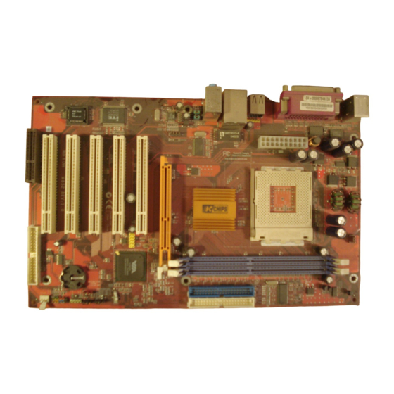
Motherboard Components Identify major components on the motherboard via this diagram underneath. Note: Any jumpers on your motherboard that do not appear in this illustration are for testing only. -
Page 24: I/O Ports
I/O Ports The illustration below shows a side view of the built-in I/O ports on the motherboard. (optional) PS/2 Mouse Use the upper PS/2 port to connect a PS/2 pointing device. PS/2 Keyboard Use the lower PS/2 port to connect a PS/2 keyboard. -
Page 25: Installing The Processor
Installing the Processor This motherboard has a Socket 462 processor socket. When choosing a processor, consider the performance requirements of the system. Performance is based on the processor design, the clock speed and system bus frequency of the processor, and the quantity of internal cache memory and external cache memory. -
Page 26: Installing Memory Modules
Installing Memory Modules This motherboard accommodates two 184-pin 2.5V unbuffered Double Data Rate (DDR) SDRAM memory modules. Each module can be installed with 128 MB to 1 GB of memory; total memory capacity is 2GB. Note: DDR SDRAM uses additional power and ground lines and requires 184-pin DIMM modules rather than the 168-pin DIMMs used by SDRAM. -
Page 27: Jumper Settings
4. Check that the cutouts on the DIMM module edge connector match the notches in the DIMM slot. 5. Install the DIMM module into the slot and press it firmly down until it seats correctly. The slot latches are levered upwards and latch on to the edges of the DIMM. -
Page 28: Install The Motherboard
Function Jumper Setting Normal Short Pins 1-2 Clear CMOS Short Pins 2-3 JP2 & JP3: CPU Frequency Select Jumper This jumper enables you to set the CPU frequency. CPU Frequency Short 1-2 Short 1-2 100MHz Short 2-3 Short 1-2 133MHz Short 1-2 Short 2-3 Not Applicable... - Page 29 Connect the chase cooling fan connector to CASFAN1. Connect the cable from the PC speaker to the SPK1 connector on the motherboard. Signal Signal SIGNAL GROUND Connect the case LED cable to the optional Single color LED connector PANEL1. Front Panel Connector The front panel connector (PANEL1) provides a standard set of switch and LED connectors commonly found on ATX or micro- ATX cases.
-
Page 30: Connecting Optional Devices
Connecting Optional Devices Refer to the following for information on connecting the motherboard’s optional devices: AUDIO1: Front Panel Audio header This header allows the user to install auxiliary front-oriented microphone and line-out ports for easier access. Signal Signal AUD_MIC AUD_GND AUD_MIC_BIAS AUD_VCC AUD_FPOUT_R... - Page 31 Signal Signal USBVCC USBVCC USBP4- USBP5- USBP4+ USBP5+ Note: Please make sure that the USB cable has the same pin assignment as indicated above. A different pin assignment may cause damage or system hang-up. USBCR1: USB Card Reader Connector (optional) This connector is for connecting internal USB card reader.
-
Page 32: Install Other Devices
Install Other Devices Install and connect any other devices in the system following the steps below. Installing a Hard Disk Drive/CD-ROM This section describes how to install IDE devices such as a hard disk drive and a CD-ROM drive. Your motherboard has a primary and secondary IDE channel interface (IDE1 and IDE2). - Page 33 IDE2: Secondary IDE The second drive on this controller must be set to slave mode. The configuration is the same as IDE1. You must orient the cable connector so that the pin 1 (color) edge of the cable corresponds to the pin 1 of the I/O port connector.
- Page 34 This connector supports the provided floppy drive ribbon cable. After connecting the single end to the onboard floppy connector, connect the remaining plugs on the other end to the floppy drives correspondingly. You must orient the cable connector so that the pin 1 (color) edge of the cable corresponds to the pin 1 of the I/O port connector.
-
Page 35: Expansion Slots
Expansion Slots The slots in this motherboard are designed to hold expansion cards and connect them to the system bus. Expansion slots are a means of adding or enhancing the motherboard’s features and capabilities. With these efficient facilities, you can increase the motherboard’s capabilities by adding hardware which performs tasks that are not part of the basic system. -
Page 36: Chapter 3: Using Bios
Chapter 3 Using BIOS About The Setup Utility The computer uses the latest Award BIOS with support for Windows Plug and Play. The CMOS chip on the mainboard contains the ROM setup instructions for configuring the mainboard BIOS. The BIOS (Basic Input and Output System) Setup Utility displays the system's configuration status and provides you with options to set system parameters. - Page 37 Starting Setup The BIOS is immediately activated when you first turn on the computer. The BIOS reads system configuration in CMOS RAM and begins the process of checking out the system and configuring it through the power-on self test (POST). When these preliminaries are finished, the BIOS seeks an operating system on one of the data storage devices (hard drive, floppy drive, etc.).
-
Page 38: Standard Cmos Setup
Standard CMOS Setup In the Standard CMOS menu you can set the system clock and calendar, record disk drive parameters and the video subsystem type, and select the type of errors that stop the BIOS POST. Phoenix – AwardBIOS CMOS Setup Utility Standard CMOS Features Item Help Date (mm:dd:yy) - Page 39 IDE HDD Auto-Detection Press <Enter> while this item is highlighted to prompt the Setup Utility to automatically detect and configure an IDE device on the IDE channel. Note: If you are setting up a new hard disk drive that supports LBA mode, more than one line will appear in the parameter box.
-
Page 40: Advanced Cmos Setup
Advanced BIOS Setup This screen contains industry-standard options additional to the core PC AT BIOS. Phoenix – AwardBIOS CMOS Setup Utility Advanced BIOS Setup Item Help Virus Warning [Disabled] CPU Internal Cache [Enabled] Menu Level External Cache [Enabled] CPU L2 Cache ECC Checking [Enabled] Allows you to choose Processor Number Feature... - Page 41 CPU L2 Cache ECC Checking (Enabled) This item enables or disables ECC (Error Correction Code) error checking on the CPU cache memory. We recommend that you leave this item at the default value. Processor Number Feature (Enabled) Some new processors are installed with a unique processor number. This number may be used for verification in Internet transactions and e-commerce.
-
Page 42: Advanced Chipset Setup
• Typematic Rate (Chars/Sec): Use this item to define how many characters per second are generated by a held-down key. • Typematic Delay (Msec): Use this item to define how many milliseconds must elapse before a held-down key begins generating repeat characters. Security Option (Setup) If you have installed password protection, this item defines if the password is required at system start up, or if it is only required when a... - Page 43 Phoenix – AwardBIOS CMOS Setup Utility Advanced Chipset Setup Item Help DRAM Clock/Drive Control [Press Enter] AGP & P2P Bridge Control [Press Enter] Menu Level CPU & PCI Bus Control [Press Enter] System BIOS Cacheable [Disabled] Video RAM Cacheable [Disabled] BIOS Flash PROTECT [Disabled] ↑...
- Page 44 DRAM Timing (Manual) Set this to the default value to enable the system to automatically set the SDRAM timing by SPD (Serial Presence Detect). SPD is an EEPROM chip on the DIMM module that stores information about the memory chips it contains, including size, speed, voltage, row and column addresses, and manufacturer.
- Page 45 DRAM Burst Length (4) This item describes which burst lengths are supported by the devices on the mainboard. 1 level can provide faster performance but may result in instability whereas 8 level gives the most stable but slowest performance. DRAM Queue Depth (4 level) This item sets the depth of the DRAM queue used for CPU’s cache.
- Page 46 AGP Driving Control (Auto) This item is used to signal driving current on AGP cards to auto or manual. Some AGP cards need stronger than normal driving current in order to operate. We recommend that you set this item to the default. •...
- Page 47 PCI Delay Transaction (Enabled) The mainboard’s chipset has an embedded 32-bit post write buffer to support delay transactions cycles. Select Enabled to support compliance with PCI specification version 2.1. Press <Esc> to return to the Advanced Chipset Setup screen. System BIOS/Video RAM Cacheable (Disabled) These items allow the video and system to be cached in memory for faster execution.
- Page 48 On-Chip IDE Channel 0/1 (Enabled) Use these items to enable or disable the PCI IDE channels that are integrated on the mainboard. IDE Prefetch Mode (Enabled) The onboard IDE drive interfaces supports IDE prefetching, for faster drive access. If you install a primary and secondary add-in IDE interface, set this field to Disabled if the interface does not support prefetching.
- Page 49 VIA OnChip PCI Device Scroll to this item and press <Enter> to view the following screen: CMOS Setup Utility – Copyright (C) 1984 – 2001 Award Software VIA OnChip PCI Device Item Help AC97 Audio [Auto] MC97 Modem [Auto] Menu Level OnChip LAN [Enabled] Onboard LAN Boot ROM...
- Page 50 SuperIO Device Scroll to this item and press <Enter> to view the following screen: CMOS Setup Utility – Copyright (C) 1984 – 2001 Award Software SuperIO Device Onboard FDC Controller [Enabled] Item Help Onboard Serial Port 1 [3F8/IRQ4] Menu Level Onboard Parallel Port [378/IRQ7] Parallel Port Mode...
-
Page 51: Power Management Setup
Power Management Setup The Power Management Setup Menu option is used to change the values of the chipset registers for system power management. Power Management Timeouts The power-saving modes can be controlled by timeouts. If the system is inactive for a time, the timeouts begin counting. If the inactivity continues so that the timeout period elapses, the system enters a power-saving mode. - Page 52 User Define, you can insert your own timeouts for the power-saving modes. HDD Power Down (Disable) The IDE hard drive will spin down if it is not accessed within a specified length of time. Options are from 1 Min to 15 Min and Disable.
- Page 53 IRQ/Event Activity Detect Scroll to this item and press <Enter> to view the following screen: Phoenix – AwardBIOS CMOS Setup Utility IRQ/Event Activity Detect Item Help [OFF] LPT & COM [LPT/COM] Menu Level HDD & FDD [ON] PCI Master [OFF] PowerOn by PCI Card [Enabled] Modem Ring Resume...
- Page 54 RTC Alarm Resume (Disabled) When set to Enabled, additional fields become available and you can set the date (day of the month), hour, minute and second to turn on your system. When set to 0 (zero) for the day of the month, the alarm will power on your system every day at the specified time.
- Page 55 Phoenix - AwardBIOS CMOS Setup Utility PnP/PCI Configurations PNP OS Installed [No] Item Help Reset Configuration Data [Disabled] Resources Controlled by [Auto(ESCD)] Menu Level x IRQ Resources Press Enter Default is Disabled. PCI/VGA Palette Snoop [Disabled] Select Enabled to reset Assign IRQ For VGA [Enabled] Extended System...
- Page 56 PCI/VGA Palette Snoop (Disabled) This item is designed to overcome some problems that can be caused by some non-standard VGA cards. This board includes a built-in VGA system that does not require palette snooping so you must leave this item disabled. Assign IRQ for VGA/USB (Enabled) Names the interrupt request (IRQ) line assigned to the USB/VGA (if any) on your system.
- Page 57 Phoenix – AwardBIOS CMOS Setup Utility Frequency Control Item Help Auto Detect DIMM/PCI Clk [Enabled] Spread Spectrum [Enabled] Menu Level CPU Clock [Default] ↑ ↓ → ← : Move Enter : Select +/-/PU/PD:Value: F10: Save ESC: Exit F1:General Help F5:Previous Values F6:Fail-Safe Defaults F7:Optimized Defaults Auto Detect DIMM/PCI Clk (Enabled)
-
Page 58: Exit Without Saving
Set Password Option This item can be used to install a password. To install a password, follow these steps: 1. Highlight the item Set Password on the main menu and press <Enter>. 2. The password dialog box appears. Enter Password: 3. -
Page 59: Chapter 4: Software & Applications
Chapter 4 Software & Applications Introduction This chapter describes the contents of the support CD-ROM that comes with the motherboard package. The support CD-ROM contains all useful software, necessary drivers and utility programs to properly run our products. More program information is available in a README file, located in the same directory as the software. -
Page 60: Installing Support Software
Installing Support Software 1.Insert the support CD-ROM disc in the CD-ROM drive. 2.When you insert the CD-ROM disc in the system CD-ROM drive, the CD automatically displays an Auto Setup screen. 3.The screen displays three buttons of Setup, Browse CD and Exit on the right side, and three others Setup, Application and ReadMe at the bottom. - Page 61 Auto-Installing under Windows 98/ME/2000/XP If you are under Windows 98/ME/2000/XP, please click the Setup button to run the software auto-installing program while the Auto Setup screen pops out after inserting the support CD-ROM: 1. The installation program loads and displays the following screen.
-
Page 62: Bundled Software Installation
Installing under Windows NT or Manual Installation If you are under Windows NT, the auto-installing program doesn’t work out; or you have to do the manual installation, please follow this procedure while the Auto Setup screen pops out after inserting the support CD-ROM: 1.
Need help?
Do you have a question about the M852 and is the answer not in the manual?
Questions and answers