Table of Contents
Advertisement
Quick Links
This publication, including all photographs, illustrations and
software, is protected under international copyright laws, with all
rights reserved. Neither this manual, nor any of the material
contained herein, may be reproduced without written consent of the
author.
The information in this document is subject to change without
notice. The manufacturer makes no representations or warranties
with respect to the contents hereof and specifically disclaims any
implied warranties of merchantability or fitness for any particular
purpose. Further, the manufacturer reserves the right to revise this
publication and to make changes from time to time in the content
hereof without obligation of the manufacturer to notify any person
of such revision or changes.
Trademarks
IBM, VGA, and PS/2 are registered trademarks of International
Business Machines.
Intel, Pentium/II/III, Pentium 4, Celeron and MMX are registered
trademarks of Intel Corporation.
Microsoft, MS-DOS and Windows 98/ME/NT/2000/XP are
registered trademarks of Microsoft Corporation.
PC-cillin is a registered trademark of Trend Micro Inc.
AMI is a registered trademark of American Megatrends Inc.
MediaRing Talk is a registered trademark of MediaRing Inc.
3Deep is a registered trademark of E-Color Inc.
SiS is a trademark of Silicon Integrated System Corporation.
Other brands or product names in this manual are trademarks or the
properties of their respective owners and are acknowledged.
Copyright © 2003
All Rights Reserved
M848 Series, V1.2
S746/March 2003
Advertisement
Table of Contents

Subscribe to Our Youtube Channel
Related Manuals for PCchips M848LU


Summary of Contents for PCchips M848LU
- Page 1 This publication, including all photographs, illustrations and software, is protected under international copyright laws, with all rights reserved. Neither this manual, nor any of the material contained herein, may be reproduced without written consent of the author. The information in this document is subject to change without notice.
- Page 2 Notice: Owing to Microsoft’s certifying schedule is various to every supplier, we might have some drivers not certified yet by Microsoft. Therefore, it might happen under Windows XP that a dialogue box (shown as below) pop out warning you this software has not passed Windows Logo testing to verify its compatibility with Windows XP.
-
Page 3: Table Of Contents
Table of Contents Chapter 1: Introduction..............1 Key Features................2 Package Contents..............5 Static Electricity Precautions...........6 Pre-Installation Inspection............6 Chapter 2: Mainboard Installation...........7 Mainboard Components ............8 I/O Ports...................8 Installing the Porcessor............10 Installing Memory Modules ..........10 Setting Jumper Switches............11 Install the Mainboard.............12 Connecting Optional Devices..........13 Install Other Devices .............16 Expansion Slots ..............17 Chapter 3: BIOS Setup Utility............19... -
Page 5: Chapter 1: Introduction
Chapter 1 Introduction This mainboard has a Socket-462 processor socket for the AMD K7 type of processors. You can install any of these processors on this mainboard. This mainboard supports front-side bus speed of 333MHz. This mainboard integrates the SiS746 Northbridge along with SiS963L Southbridge chipsets that supports built-in AC97 Codec support 6-channel speak-out, 2 DDR333 modules up to 2GB system memory. -
Page 6: Key Features
Key Features The key features of this mainboard include: Socket-462 Processor Support ♦ Supports AMD Athlon XP/Athlon/Duron processors ♦ Supports 333 MHz Front-Side Bus Chipset There are SiS746 Northbridge and SiS963L Southbridge in this chipset in accordance with an innovative and scalable architecture with proven reliability and performance. - Page 7 AC97 Audio Codec ♦ 6-CH hardware architecture allows multi-channel south bridge to playback 6CH audio ♦ Intel AC’97 (REV. 2.2) compatible, meeting Microsoft PC2001 requirements ♦ Built-in earphone buffer and internal PLL, the latter saving additionsl crystal ♦ Line-in/rear out share the same jack; Center/bass share the MIC jack ...
- Page 8 ♦ Compliant with Intel’s Enhanced Host Controller Interface Specification Revision 0.95 ♦ Compliant with Universal Host Controller Interface Specification Revision 1.1 ♦ PCI multi-function device consists of two UHCI Host Controller cores for full-/low-speed signaling and one EHCI Host Controller core for high-speed signaling ♦...
-
Page 9: Package Contents
Package Contents Attention: This mainboard serial has two models, M848LU(LAN, USB2.0), and M848U(USB2.0). Please contact your local supplier for more information about your purchased model. Each model will support different specification listed as below: Model Specification M848LU Onboard LAN PHY chip, USB2.0... -
Page 10: Static Electricity Precautions
Static Electricity Precautions Static electricity could damage components on this mainboard. Take the following precautions while unpacking this mainboard and installing it in a system. 1. Don’t take this mainboard and components out of their original static-proof package until you are ready to install them. 2. -
Page 11: Chapter 2: Mainboard Installation
Chapter 2 Mainboard Installation To install this mainboard in a system, please follow the instructions in this chapter: Identify the mainboard components Install a CPU Install one or more system memory modules Verify that all jumpers or switches are set correctly Install the mainboard in a system chassis (case) Connect any extension brackets or cables to connecting headers on the mainboard... -
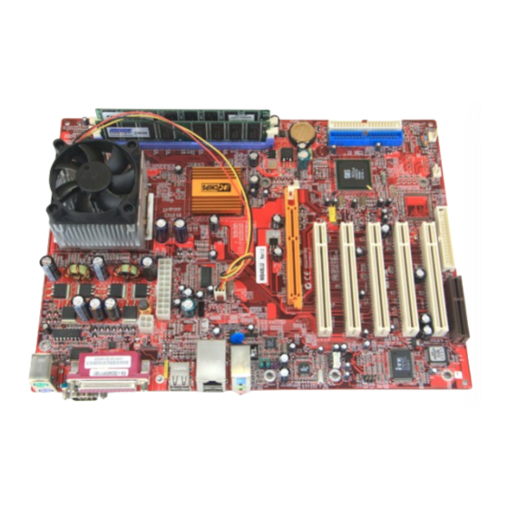
Page 12: Mainboard Components
Mainboard Components Identify major components on the mainboard via this diagram underneath. Note: Any jumpers on your mainboard not appearing in the illustration above are for testing only. I/O Ports The illustration below shows a side view of the built-in I/O ports on the mainboard. - Page 13 PS/2 Mouse Use the upper PS/2 port to connect a PS/2 pointing device. PS/2 Keyboard Use the lower PS/2 port to connect a PS/2 keyboard. Parallel Port Use the Parallel port (LPT1) to connect (LPT1) printers or other parallel communications devices.
-
Page 14: Installing The Porcessor
Installing the Processor This mainboard has a Socket 462 processor socket. When choosing a processor, consider the performance requirements of the system. Performance is based on the processor design, the clock speed and system bus frequency of the processor, and the quantity of internal cache memory and external cache memory. -
Page 15: Setting Jumper Switches
DDR SDRAM provides 1.6 GB/s or 2.1 GB/s data transfer rate depending on whether the bus is 100MHz, 133MHz or 166MHz. DDR SDRAM uses additional power and ground lines and requires 184-pin 2.5V unbuffered DIMM module. DDR1 DDR2 Installation Procedure These modules can be installed with up to 2 GB system memory. -
Page 16: Install The Mainboard
Jumper JP3: Clear CMOS Memory Use this jumper to clear the contents of the CMOS memory. You may need to clear the CMOS memory if the settings in the Setup Utility are incorrect and prevent your mainboard from operating. To clear the CMOS memory, disconnect all the power cables from the mainboard and then move the jumper cap into the CLEAR setting for a few seconds. -
Page 17: Connecting Optional Devices
Connect the power connector from the power supply to the ATXPW1 connector on the mainboard. CN1 is the CPU Vcore power connector. If there is a cooling fan installed in the system chassis, connect the cable from the cooling fan to the SYSTEMFAN/CHASISFAN fan power connector on the mainboard. - Page 18 Signal Signal AUD_MIC AUD_GND AUD_MIC_BIAS AUD_VCC AUD_FPOUT_R AUD_RET_R HP_ON AUD_FPOUT_L AUD_RET_L USB3: Front panel USB Connector The mainboard has USB ports installed on the rear edge I/O port array. Additionally, some computer cases have USB ports at the front of the case. If you have this kind of case, use auxiliary USB connector USB3 to connect the front-mounted ports to the mainboard.
- Page 19 Please check the pin assignment of the cable and the USB header on the mainboard. Make sure the pin assignment will match before plugging in. Any incorrect usage may cause unexpected damage to the system. The vendor won’t be responsible for any incidental or consequential damage arising from the usage or misusage of the purchased product.
-
Page 20: Install Other Devices
Install Other Devices Install and connect other devices in the system as steps below. FDC1 IDE1 IDE2 Floppy Disk Drive The mainboard ships with a floppy disk drive cable that can support one or two drives. Drives can be 3.5” or 5.25” wide, with capacities of 360K, 720K, 1.2MB, 1.44MB, or 2.88MB. -
Page 21: Expansion Slots
Internal Sound Connections If you have installed a CD-ROM drive or DVD-ROM drive, you can connect the drive audio cable to the onboard sound system. CD_IN1 CD_IN2 When you first start up your system, the BIOS should automatically detect your CD-ROM/DVD drive. If it doesn’t, enter the Setup Utility and configure the CD-ROM/DVD drive that you have installed. - Page 22 Follow the steps below to install an AGP/CNR/PCI expansion card. 1. Locate the AGP, PCI or CNR slot on the mainboard. 2. Remove the slot cover from the system chassis. 3. Insert the expansion card edge connector into the slot and press it firmly down until fully inserted.
-
Page 23: Chapter 3: Bios Setup Utility
Chapter 3 BIOS Setup Utility Introduction The BIOS Setup Utility records settings and information about your computer such as the date and time, the kind of hardware installed, and various configuration settings. Your computer uses this information to initialize all the components when booting up and functions as the basis for coordination between system components. -
Page 24: Running The Setup Utility
Running the Setup Utility Each time your computer starts, before the operating system loads, a message appears on the screen that prompts you to “Hit <DEL> if you want to run SETUP”. When you see this message, press the Delete key and the Main menu page of the Setup Utility appears on your monitor. -
Page 25: Standard Cmos Setup Page
Standard CMOS Setup Page This page sets up basic information such as the date, the time, the IDE devices, and the diskette drives. If you press the F3 key, the system will automatically detect and configure the hard disks on the IDE channels. -
Page 26: Advanced Setup Page
Advanced Setup Page This page sets up more advanced information about your system. Take care of this page with more caution. Any changes can affect the operation of your computer. AMIBIOS SETUP – ADVANCED SETUP (C) 2000 American Megatrends, Inc. All Rights Reserved Quick Boot Enabled Card Reader Boot Function... - Page 27 S.M.A.R.T. for Hard Enable this item if any IDE hard disks Disks support the S.M.A.R.T. (Self- Monitoring, Analysis and Reporting Technology) feature. BootUp Num-Lock This item determines if the Num Lock key is active or inactive at system start- up time. Floppy Drive Swap If you have two diskette drives installed and you enable this item, drive A...
- Page 28 DRAM CAS# Latency This item determines the operation of DRAM memory CAS (column address strobe). It is recommended that you leave this item at the default value. The 3T setting requires faster memory that specifically supports this mode. Timing Setting Mode This item determines the timing setting mode of the memory.
-
Page 29: Power Management Setup Page
Power Management Setup Page This page sets some of the parameters for system power management operation. AMIBIOS SETUP – POWER MANAGEMENT SETUP (C) 2000 American Megatrends, Inc. All Rights Reserved ACPI Aware O/S Power Management Enabled Suspend Time out Disabled Hard Disk Time out Disabled Resume On RTC Alarm... -
Page 30: Pci/Plug And Play Setup Page
LAN/Ring Power The system can be turned off with a software command. If you enable this item, the system can automatically resume if there is an incoming call on the Modem. You must use an ATX power supply in order to use this feature. -
Page 31: Load Optimal Settings
Primary Graphics This item indicates if the primary graphics Adapter adapter uses the PCI or the AGP bus. The default PCI setting still lets the onboard display work and allows the use of a second display card installed in a PCI slot. Allocate IRQ to If this item is enabled, an IRQ will be PCI VGA... -
Page 32: Features Setup Page
Features Setup Page This page sets some of the parameters for peripheral devices connected to the system. AMIBIOS SETUP – FEATURES SETUP (C) 2000 American Megatrends, Inc. All Rights Reserved OnBoard FDC Enabled OnBoard Serial PortA 3F8h/COM1 OnBoard IR Port Disabled OnBoard Parallel Port 378h... - Page 33 Parallel Port DMA Use this item to assign a DMA channel to the parallel port. The options are 0, 1 and 3. Onboard PCI IDE Use this item to enable or disable either or both of the onboard Primary and Secondary IDE channels.
-
Page 34: Cpu Pnp Setup Page
CPU PnP Setup Page This page lets you manually configure the mainboard for the CPU. The system will automatically detect the kind of CPU that you have installed and make the appropriate adjustments to the items on this page. AMIBIOS SETUP – CPU PnP SETUP ©2000 American Megatrends, Inc. -
Page 35: Hardware Monitor Page
Hardware Monitor Page This page sets some of the parameters for the hardware monitoring function of this mainboard. AMIBIOS SETUP – HARDWARE MONITOR (C) 2000 American Megatrends, Inc. All Rights Reserved *** System Hardware *** CPU Vcore 1.616V Vcc 2.5V 2.496V +3.3V 3.392V... -
Page 36: Exit
Change or Remove the Password Highlight this item, press Enter and type in the current password. At the next dialog box, type in the new password, or just press Enter to disable password protection. Exit Highlight this item and press Enter to save the changes that you have made in the Setup Utility configuration and exit the program. -
Page 37: Chapter 4: Software & Applications
Chapter 4 Software & Applications Introduction This chapter describes the contents of the support CD-ROM that comes with the mainboard package. The support CD-ROM contains all useful software, necessary drivers and utility programs to properly run our products. More program information is available in a README file, located in the same directory as the software. -
Page 38: Installing Support Software
Installing Support Software 1.Insert the support CD-ROM disc in the CD-ROM drive. 2.When you insert the CD-ROM disc in the system CD-ROM drive, the CD automatically displays an Auto Setup screen. 3.The screen displays three buttons of Setup, Browse CD and Exit on the right side, and three others Setup, Application and ReadMe at the bottom. - Page 39 Auto-Installing under Windows 98/ME/2000/XP If you are under Windows 98/ME/2000/XP, please click the Setup button to run the software auto-installing program while the Auto Setup screen pops out after inserting the support CD-ROM: 1. The installation program loads and displays the following screen.
-
Page 40: Bundled Software Installation
Installing under Windows NT or Manual Installation If you are under Windows NT, the auto-installing program doesn’t work out; or you have to do the manual installation, please follow this procedure while the Auto Setup screen pops out after inserting the support CD-ROM: 1. -
Page 41: Set Up The Audio System
Set Up the Audio System Set up the Audio configuration of 2-channel, 4-channel and 6- channel speaker-out system through the audio driver. It also provides users with Xear Technology, the virtual rear sound effect compensation for any multi-channel audio systems simply by using a pair of open-aired headphones. - Page 42 Xear 3D Mode In Xear 3D Mode, there are Virtual Speaker Shifter/Advance and Earphone Plus Mode options and channel selections. Each channel has a corresponding position of phone jacks and description. (Three audio jacks on the screen show these colors: top-- lime, middle-- light blue, bottom-- pink) EARPHONE 2-CHANNEL...
- Page 43 FOUR-CHANNEL SIX-CHANNEL Earphone Plus Mode While enabling Earphone Plus Mode, it activates the Xear function; moreover, original Front Out and Rear Out positions will be exchanged in Multi-Channel mode. EARPHONE and 2-CHANNEL don’t support Xear function. (Three audio jacks on the screen show these colors: top-- lime, middle-- light blue, bottom-- pink)
- Page 44 FOUR-CHANNEL SIX-CHANNEL...
- Page 45 Virtual Speaker Shift/Advance Click the Virtual Speaker Shift/Advance button, it provides some 3D Sound Effect and DEMO program for testing.
Need help?
Do you have a question about the M848LU and is the answer not in the manual?
Questions and answers