Table of Contents
Advertisement
Quick Links
This publication, photographs, illustrations and software are under
the protection of international copyright laws and all rights
reserved. It does not allow any reproduction of this manual, content
and any materials contained herein without the written consent of
the authentic manufacturer.
The information in this manual is subject to change without notice.
The manufacturer does neither represent nor warrant the contents
hereof; and specifically disclaims any implied warranties of
merchantability or fitness for any particular purpose. Furthermore,
the manufacturer reserves the right to revise and change this
publication from time to time, without the obligation of notifying
any person of such revision or changes.
Trademarks
IBM, VGA, and PS/2 are registered trademarks of International
Business Machines.
AMD, Duron and Athlon are registered trademarks of Advanced
Micro Devices Inc.
Microsoft, MS-DOS and Windows 98/ME/NT/2000/XP are
registered trademarks of Microsoft Corporation.
PC-cillin is a trademark of Trend Micro Inc.
AMI is a trademark of American Megatrends Inc.
MediaRing Talk is a registered trademark of MediaRing Inc.
3Deep is a registered trademark of E-Color Inc.
It has been acknowledged that all mentioned brands or product
names are trademarks or registered trademarks of their respective
holders.
Copyright © 2003
All Rights Reserved
M848A Series, V2.1
S748/August 2003
Advertisement
Table of Contents

Subscribe to Our Youtube Channel
Related Manuals for PCchips M848ALU


Summary of Contents for PCchips M848ALU
- Page 1 This publication, photographs, illustrations and software are under the protection of international copyright laws and all rights reserved. It does not allow any reproduction of this manual, content and any materials contained herein without the written consent of the authentic manufacturer. The information in this manual is subject to change without notice.
-
Page 2: Table Of Contents
Table of Contents Trademark ..................I Static Electricity Precautions..........III Pre-Installation Inspection.............III Features & Checklist Translations ..........V Chapter 1: Introduction..............1 Key Features................2 Package Contents..............5 Chapter 2: Mainboard Installation..........6 Mainboard Components ............7 I/O Ports...................8 Installing the Processor............9 Installing Memory Modules ..........10 Jumper Settings ..............11 Install The Mainboard ............12 Connecting Optional Devices..........13 Install Other Devices .............16... -
Page 3: Static Electricity Precautions
Static Electricity Precautions Static electricity could damage components on this mainboard. Take the following precautions while unpacking this mainboard and installing it in a system. 1. Don’t take this mainboard and components out of their original static-proof package until you are ready to install them. 2. - Page 4 USB devices’ connection because it could not recognize these devices. Currently, we are working on such limitations’ solution. As soon as the solution is done, the updated USB drive will be released to our website: www.pcchips.com.tw for your downloading.
-
Page 5: Features & Checklist Translations
Features and Checklist Translations Liste de contrôle Comparez ce qui est contenu dans l'emballage de la carte mère avec la liste suivante: Eléments standards • Une carte mère • Un câble plat pour lecteur de disquette (optionnel) • Un câble plat pour lecteur IDE •... - Page 6 MAC, interface AC97, gestion d’alimentation avancée, contrôleur DMA et contrôleur de clavier intégrés. • Mémoire Support de module mémoire DDR SDRAM jusqu’à 266/333/400 MHz • Peut recevoir trois logements sans mémoire tampon en 2.5V de 184 broches • Chaque logement supporte jusqu’à 1 Go avec une capacité...
- Page 7 LAN Interne Le VT6103L est un périphérique à Couche Physique (optionnel) pour Ethernet 10BASE-T et 100BASE-TX utilisant des câbles Non blindés de catégorie 5, Blindés de Type 1, et à Fibres Optiques. • Double Vitesse – 100/10 Mbps • Half et Full Duplex •...
- Page 8 Checkliste Vergleichen Sie den Packungsinhalt des Motherboards mit der folgenden Checkliste: Standard Items • Ein Motherboard • Ein Bandkabel für Diskettenlaufwerke (optional) • Ein Bandkabel für IDE-Laufwerke • Eine Auto-Installations-Support-CD • I/O-Anschlussabdeckung für die Rückwand • Dieses Benutzerhandbuch Features Prozessor Das Mainboard verwendet einen AMD 462-Pin Sockel A, der einen 400 MHz Frontsidebus (FSB) unterstützt.
- Page 9 • Unterstützt DDR bis zu 266/333/400 MHz SDRAM- Speicher Speichermodul • Nimmt drei ungepufferte 2.5V 184-Pin Steckplätze • Jeder Steckplatz unterstützt bis zu 1 GB mit einer maximalen Gesamtkapazität von bis zu 3 GB Grafik Das M848A enthält einen AGP-Steckplatz mit der achtfachen Bandbreite der ursprünglichen AGP- Spezifikation.
- Page 10 Integrierte I/O Das Mainboard verfügt über einen kompletten Satz von I/O-Schnittstellen und Anschlüssen: • Zwei PS/2-Schnittstellen für Maus und Tastatur • Zwei serielle Schnittstellen (COM2 ist optional) • Eine parallele Schnittstelle • Vier USB-Schnittstellen • Eine LAN-Schnittstelle • Audiobuchsen für Mikrofon, Line-in und Line-out BIOS-Firmware Dieses Mainboard setzt das AMI BIOS ein, mit dem der Anwender viele Systemeigenschaften selbst...
- Page 11 Lista di controllo Comparate il contenuto della confezione della scheda madre con la seguente lista di controllo: Articoli standard • Una scheda madre • Un cavo a nastro per il drive dischetti (opzionale) • Un cavo a nastro IDE • Un CD di supporto software auto-installante •...
- Page 12 • Supporta un modulo di memoria SDRAM con DDR Memoria fino a 266/333/400 Mhz • Presenta tre slot a 184 pin 2,5 V unbuffered • Ciascun slot supporta fino a 1 GB per una capacità totale massima di 3 GB Grafica La scheda M848A include uno slot AGP che fornisce otto volte la larghezza di banda delle specifiche AGP...
- Page 13 Inizializza I/O La scheda madre è dotata da una serie completa di porte e connettori I/O: • Due porte PS/2 per tastiera e mouse • Due porte seriali (la porta COM2 è opzionale) • Una porta parallela • Quattro porte USB •...
- Page 14 Lista de Verificación Compare los contenidos del paquete de la placa principal con la sigte. lista: Ítems Estándares • Una placa principal • Un cable cinta del lector de diskette (optativo) • Un cable cinta de la unidad IDE • Un CD de soporte en software de autoinstalación •...
- Page 15 • Soporta DDR hasta módulo de memoria Memoria 266/333/400 MHz SDRAM • Acomoda tres ranuras 2.5V 184-pin sin buffer • Cada ranura soporta hasta 1 GB con una capacidad máxima total de 3 GB Gráficas El M848A incluye una ranura AGP que provee ocho veces la ancha de banda de la especificación de AGP original.
- Page 16 I/O Integrado La placa principal tiene un juego completo de puertos y conectores I/O: • Dos puertos PS/2 para ratón y teclado • Dos puertos serials (COM2 es optativo) • Un puerto paralelo • Cuatro puertos USB • Un puerto LAN •...
- Page 17 Lista de verificação A embalagem da sua placa principal contém os seguintes itens: A placa principal O Manual do Utilizador Um cabo para a unidade de disquetes (opcional) Um cabo para a unidade IDE CD de suporte para o software Características Processador A placa principal usa um AMD 462-pin Socket A que...
- Page 18 Gráficos A placa principal inclui um encaixe AGP que fornece uma banda oito vezes maior do que a especificação AGP original. O AGP 3.0 (8x AGP) oferece um aumento significante de performance assim com características de realce do AGP2.0. Este interface representa a evolução natural do AGP existente procurando satisfazer a demanda crescente dos gráficos interface dentro da estação de trabalaho e do...
- Page 19 • Um porte de LAN • Jacks audio para microfone, line-in e line-out BIOS Esta placa usa AMI BIOS que permite os usuários Firmware configurar várias características do sistea inclusive o seguinte: • Administração de Força • Alarmes para Acordar •...
- Page 20 校验表 将本主板的组件内容与以下校验表进行对照: 标准组件 • 一只主板 • 一条磁盘驱动器带状电缆 (可选) • 一条 IDE 驱动器带状电缆 • 一张自动安装软件支持光盘 • 一个后面板 I/O 防护罩 • 本用户手册 特性 处理器 主板使用一个 AMD 462-pin Socket A 插座,支持 400 MHz 前端总线 (FSB)。 芯片组 SiS748 和 SiS963L 芯片组是基于一种新型的、可扩展 的架构,能提供已经证明的可靠性和高性能。此芯片组 具有以下一些高级功能: • 支持...
- Page 21 • 支持 266/333/400MHz DDR SDRAM 内存条 内存 • 它有 3 个非缓冲 2.5V 184 pin 插槽 • 每个插槽支持 1 GB,总共最大可支持 3 GB M848A 包括一个 AGP 插槽,可提供普通 AGP 规格 8-倍 图形 的带宽。AGP 3.0 (8xAGP) 在增强了 AGP2.0 功能的同 时极大地提高了性能。此接口反映了 AGP 的发展规律, 它进一步满足了在工作站和桌面环境中对图形接口的不 断增长的要求。 音频...
- Page 22 能: • 电源管理 • 唤醒报警 • CPU 参数 • CPU 和记忆定时 还可用于设置不同处理器时钟速度的参数。 部分硬件规格和软件项目若有更改恕不另行通知。 XXII...
-
Page 23: Chapter 1: Introduction
Chapter 1 Introduction Thank you for choosing M848A mainboard. The mainboard is designed to fit the advanced AMD processors in the 462-pin package. Based on the ATX form factor featuring the SiS748 Northbridge and SiS963L Southbridge chipsets. The mainboard incorporates the SiS748 Northbridge and SiS963L Southbridge chipsets. -
Page 24: Key Features
Key Features This mainboard has these key features: Processor The mainboard uses an AMD 462-pin Socket A that supports 400 MHz frontside bus (FSB). Chipset The SiS748 and SiS963L chipsets are based on an innovative and scalable architecture with proven reliability and performance. A few of the chipset’s advanced features are: ♦... - Page 25 Memory ♦ Supports DDR up to 266/333/400 MHz SDRAM memory module ♦ Accommodates three unbuffered 2.5V 184-pin slots ♦ Each slot supports up to 1 GB with a total maximum capacity of 3 GB Graphics ♦ The mainboard includes an AGP slot that provides eight times the bandwidth of the original AGP specification.
- Page 26 Onboard LAN (optional) The VT6103L is a Physical Layer device for Ethernet 10BASE-T and 100BASE-TX using category 5 Unshielded, Type 1 Shielded, and Fiber Optic cables. ♦ Dual Speed – 100/10 Mbps ♦ Half And Full Duplex ♦ Meet All Applicable IEEE 802.3, 10Base-T and 100Base- Tx Standards ♦...
-
Page 27: Package Contents
Package Contents Attention: This mainboard serial has two models, M848ALU (LAN, USB2.0) and M848AU (USB2.0). Please contact your local supplier for more information about your purchased model. Each model will support different specification listed as below: Model Specification M848ALU Onboard LAN PHY chip and USB 2.0... -
Page 28: Chapter 2: Mainboard Installation
Chapter 2 Mainboard Installation To install this mainboard in a system, please follow these instructions in this chapter: Identify the mainboard components Install a CPU Install one or more system memory modules Make sure all jumpers and switches are set correctly Install this mainboard in a system chassis (case) Connect any extension brackets or cables to connectors on the mainboard... -
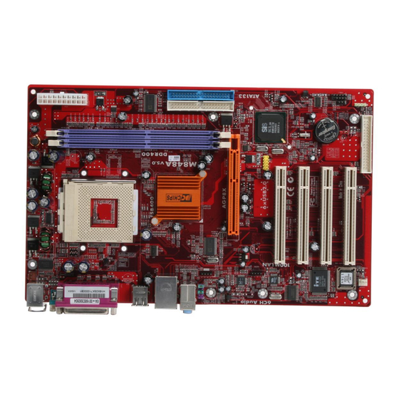
Page 29: Mainboard Components
Mainboard Components Identify major components on the mainboard via this diagram underneath. Note: Any jumpers on your mainboard that do not appear in this illustration are for testing only. -
Page 30: I/O Ports
I/O Ports The illustration below shows a side view of the built-in I/O ports on the mainboard. (optional) PS/2 Mouse Use the upper PS/2 port to connect a PS/2 pointing device. PS/2 Keyboard Use the lower PS/2 port to connect a PS/2 keyboard. -
Page 31: Installing The Processor
Installing the Processor This mainboard has a Socket 462 processor socket. When choosing a processor, consider the performance requirements of the system. Performance is based on the processor design, the clock speed and system bus frequency of the processor, and the quantity of internal cache memory and external cache memory. -
Page 32: Installing Memory Modules
Installing Memory Modules This mainboard accommodates three 184-pin 2.5V unbuffered Double Data Rate (DDR) SDRAM memory modules. The memory chips must be standard or registered SDRAM (Synchronous Dynamic Random Access Memory). You can install 3 unbuffered DIMM DDR 266/333 or 2 unbuffered DIMM DDR 400. Each module can be installed with 32 MB to 1 GB of memory;... -
Page 33: Jumper Settings
cutout on the DIMM module with the notch on the DIMM socket. 3. Install the DIMM module into the socket and press it firmly down until it is seated correctly. The socket latches are levered upwards and latch on to the edges of the DIMM. -
Page 34: Install The Mainboard
Function Jumper Setting Normal Short Pins 1-2 Clear CMOS Short Pins 2-3 Install the Mainboard Install the mainboard in a system chassis (case). The board is an ATX size mainboard. You can install this mainboard in an ATX case. Make sure your case has an I/O cover plate matching the ports on this mainboard. -
Page 35: Connecting Optional Devices
Front Panel Connector The front panel connector (PANEL1) provides a standard set of switch and LED connectors commonly found on ATX or micro- ATX cases. Refer to the table below for information: Signal Signal HD_LED_P SUS LED HD_LED_N SUS LED RST_SW_N PWR_SW_P RST_SW_P... - Page 36 AUDIO1: Front Panel Audio Connector This connector allows the user to install auxiliary front-oriented microphone and line-out ports for easier access. Signal Signal AUD_MIC AUD_GND AUD_MIC_BIAS AUD_VCC AUD_FPOUT_R AUD_RET_R HP_ON AUD_FPOUT_L AUD_RET_L USB3: Front panel USB connectors The mainboard has four USB ports installed on the rear edge I/O port array.
- Page 37 The USBCR1 is shared with one of the USB ports of the I/O back panel. The USB port is located near the Parallel port connector. See “I/O Ports” for more information. Please check the pin assignment of the cable and the USB header on the mainboard.
-
Page 38: Install Other Devices
Install Other Devices Install and connect any other devices in the system following the steps below. IDE2 IDE1 FDD1 Floppy Disk Drive The mainboard ships with a floppy disk drive cable that can support one or two drives. Drives can be 3.5” or 5.25” wide, with capacities of 360K, 720K, 1.2MB, 1.44MB, or 2.88MB. -
Page 39: Expansion Slots
If you want to install more IDE devices, you can purchase a second IDE cable and connect one or two devices to the Secondary IDE channel connector IDE2 on the mainboard. If you have two devices on the cable, one must be Master and one must be Slave. Internal Sound Connections If you have installed a CD-ROM drive or DVD-ROM drive, you can connect the drive audio cable to the onboard sound system. - Page 40 PCI1 PCI2 PCI3 PCI4 PCI5 Follow the steps below to install an AGP/CNR/PCI expansion card. 1. Locate the AGP or PCI slots on the mainboard. 2. Remove the slot cover for this slot from the system chassis. 3. Insert the expansion card edge connector into the slot and press it firmly down into it so that it is fully inserted.
-
Page 41: Chapter 3: Using Bios
Chapter 3 Using BIOS About The Setup Utility The computer uses the latest AMI BIOS with support for Windows Plug and Play. The CMOS chip on the mainboard contains the ROM setup instructions for configuring the mainboard BIOS. The BIOS (Basic Input and Output System) Setup Utility displays the system's configuration status and provides you with options to set system parameters. -
Page 42: Running The Setup Utility
• when changing the password or making other changes to the Security Setup Running the Setup Utility Each time your computer starts, before the operating system loads, a message appears on the screen that prompts you to “Hit <DEL> if you want to run SETUP”. When you see this message, press the Delete key and the Main menu page of the Setup Utility appears on your monitor. -
Page 43: Standard Cmos Setup
changes to the original values. Press F6 to install the setup utility with a set of high-performance values. Standard CMOS Setup The Standard CMOS setup is used to modify basic system configuration data, such as date, time floppy and hard disk drive types, video type and keyboard. -
Page 44: Advanced Cmos Setup
Advanced CMOS Setup The Advanced CMOS setup is used to control advanced system information such as hardware access and boot settings. Quick Boot (Enabled) If you enable this item, the system starts up more quickly be elimination some of the power on test routines. Pri/Sec Master ARMD Emulated as (Auto) Pri/Sec Slave ARMD Emulated as (Auto) These four options ensure that, if you have an ARMD attached as a... - Page 45 Initial Display Mode (BIOS) This option specifies the initial display mode when the system boots. Display Mode at Add-On ROM Init (Force BIOS) This option allows OEM logo to show during boot-up. Floppy Access Control (Read-Write) This option specifies the read/write access that is set when booting from a floppy drive.
- Page 46 Primary Display (VGA/EGA) This option configures the type of monitor attached to the computer. Password Check (Setup) This option enables password checking every time the system boots or when you run the BIOS Setup. If you choose Always, a user password prompt appears every time the computer is turned on.
-
Page 47: Advanced Chipset Setup
Advanced Chipset Setup The Advanced Chipset Setup option is used to change the values of the chipset registers. These registers control most of the system options in the computer. You should leave the items on this page at their default values, if you change the values incorrectly, you may introduce fatal errors or recurring instability into your system. - Page 48 Auto Detect DIMM/PCI Clk (Enabled) When this item is enabled, BIOS will disable the clock signal of free DIMM and PCI slots. Clock Spread Spectrum Enable (Enabled) The Clock Spread Spectrum significantly reduces the EMI (Electro Magnetic Interference) generated by the system. On Board LAN (Enabled) Enables and disables the onboard LAN.
-
Page 49: Power Management Setup
symmetric multi-processing (SMP) for systems, allowing support for up to 60 processors. DDR CAS to Latency (SPD) This item determines the operation of the DDR memory CAS (column address strobe). We recommend that you leave this item at the default value. AGP Fast Write (Disabled) Enabling this item increases the graphic performance considerably. - Page 50 ACPI Aware O/S (Yes) Set this option to Yes to enable Advanced Configuration and Power Interface (ACPI) BIOS for an ACPI-aware operating system. ACPI Standby State (S1) This item allows you to select the standby type under ACPI operating system. Power Management (Enabled) Set this option to Enabled to enable the chipset power management and APM (Advanced Power Management) features.
-
Page 51: Pci/Plug And Play Setup
Wake on Ring/LAN (Disabled) The system can be turned off with a software command. If you enable this item, the system can automatically resume if there is an incoming call on the Modem. You must use an ATX power supply in order to use this feature. - Page 52 Primary Graphics Adapter (PCI) If you are going to use an AGP graphics card, set this item to AGP. Your system will attempt to initialize the AGP card first. But if you have PCI graphics card then leave this item to its default setting. Allocate IRQ to PCI VGA (Yes) This option will be used to allocate IRQ for PCI VGA card.
-
Page 54: Peripheral Setup
determine if the BIOS should remove an IRQ from the pool of available IRQs passed to devices that are configurable by the system BIOS. The available IRQ pool is determined by reading the ESCD NVRAM. If more IRQs must be removed from the pool, the end user can use these options to reserve the IRQ by assigning an ISA/EISA setting to it. - Page 55 USB Ports Supports (Enabled) Enable this item if you plan to use the USB ports on this mainboard. USB Function (Enabled) Enable this item if you plan to use the USB ports on this mainboard. USB KB/Mouse/FDD Legacy Support (Enabled) Set this item to enable to support for older keyboard, mouse and legacy devices if the USB option is set to enable.
-
Page 56: Hardware Monitor Page
Parallel Port IRQ (Auto) Use this item to assign either IRQ 5 or 7 to the parallel port. Parallel Port DMA (Auto) Use this item to assign a DMA channel to the parallel port. The options are 0, 1 and 3. Onboard PCI IDE (Both) Use this item to enable or disable either or both of the onboard Primary and Secondary IDE channels. -
Page 58: Change Supervisor/User Password
Change Supervisor/User Password When this function is selected, the following message appears at the center of the screen to assist you in creating a password. ENTER PASSWORD Type the password, up to eight characters, and press <Enter>. The password typed now will clear any previously entered password from CMOS memory. -
Page 59: Auto Configuration With Fail Safe Settings
Auto Configuration with Fail Safe Settings This option opens a dialog box that lets you install fail-safe defaults for all appropriate items in the Setup Utility: Press <Y> and then <Enter> to install the defaults. Press <N> and then <Enter> to not install the defaults. The fail-safe defaults place no great demands on the system and are generally stable. -
Page 60: Chapter 4: Software & Applications
Chapter 4 Software & Applications Introduction This chapter describes the contents of the support CD-ROM that comes with the mainboard package. The support CD-ROM contains all useful software, necessary drivers and utility programs to properly run our products. More program information is available in a README file, located in the same directory as the software. -
Page 62: Installing Support Software
Installing Support Software 1.Insert the support CD-ROM disc in the CD-ROM drive. 2.When you insert the CD-ROM disc in the system CD-ROM drive, the CD automatically displays an Auto Setup screen. 3.The screen displays three buttons of Setup, Browse CD and Exit on the right side, and three others Setup, Application and ReadMe at the bottom. - Page 63 Auto-Installing under Windows 98/ME/2000/XP If you are under Windows 98/ME/2000/XP, please click the Setup button to run the software auto-installing program while the Auto Setup screen pops out after inserting the support CD-ROM: 1. The installation program loads and displays the following screen.
-
Page 64: Bundled Software Installation
Installing under Windows NT or Manual Installation If you are under Windows NT, the auto-installing program doesn’t work out; or you have to do the manual installation, please follow this procedure while the Auto Setup screen pops out after inserting the support CD-ROM: 1.
Need help?
Do you have a question about the M848ALU and is the answer not in the manual?
Questions and answers