Table of Contents
Advertisement
Quick Links
Mainboard User's Manual
This publication, including all photographs, illustrations and
software, is protected under international copyright laws, with all
rights reserved. Neither this manual, nor any of the material
contained herein, may be reproduced without written consent of
the author.
The information in this document is subject to change without
notice. The manufacturer makes no representations or warranties
with respect to the contents hereof and specifically disclaims any
implied warranties of merchantability or fitness for any particular
purpose. Further, the manufacturer reserves the right to revise this
publication and to make changes from time to time in the content
hereof without obligation of the manufacturer to notify any person
of such revision or changes.
Trademarks
IBM, VGA, and PS/2 are registered trademarks of International
Business Machines.
AMD, Duron and Athlon are registered trademarks of Advanced
Micro Devices Inc.
Microsoft, MS-DOS and Windows 98/ME/NT/2000/XP are
registered trademarks of Microsoft Corporation.
PC-cillin is a registered trademark of Trend Micro Inc.
AMI is a registered trademark of American Megatrends Inc.
A3D is a registered trademark of Aureal Inc.
MediaRing Talk is a registered trademark of MediaRing Inc.
3Deep is a registered trademark of E-Color Inc.
SiS is a trademark of Silicon Integrated System Corporation.
Other names used in this publication may be trademarks and are
acknowledged.
Copyright © 2002
All Rights Reserved
M830 Series, V5.0
S735/December 2002
Advertisement
Table of Contents

Subscribe to Our Youtube Channel
Related Manuals for PCchips M830LU


Summary of Contents for PCchips M830LU
- Page 1 Mainboard User’s Manual This publication, including all photographs, illustrations and software, is protected under international copyright laws, with all rights reserved. Neither this manual, nor any of the material contained herein, may be reproduced without written consent of the author. The information in this document is subject to change without notice.
- Page 2 Mainboard User’s Manual Notice: Owing to Microsoft’s certifying schedule is various to every supplier, we might have some drivers not certified yet by Microsoft. Therefore, it might happen under Windows XP that a dialogue box (shown as below) pop out warning you this software has not passed Windows Logo testing to verify its compatibility with Windows XP.
-
Page 3: Table Of Contents
Mainboard User’s Manual Table of Contents Trademarks................I Chapter 1: Introduction..............1 Key Features................2 Package Contents..............5 Static Electricity Precautions..........6 Pre-Installation Inspection............6 Chapter 2: Mainboard Installation..........7 Mainboard Components............8 I/O Ports..................8 Install A CPU................9 Install Memory..............10 Setting Jumper Switches............11 Install the Mainboard............12 Optional Extension Brackets..........13 Install Other Devices............14 Expansion Slots..............16 Chapter 3: BIOS Setup Utility............19... - Page 4 Mainboard User’s Manual...
-
Page 5: Chapter 1: Introduction
1: Introduction Chapter 1 Introduction This mainboard has a Socket-A processor socket for the type of AMD K7 processors. You can install any one of these processors on the mainboard. The mainboard supports front-side bus speeds of 266MHz. This mainboard uses the SiS735 chipset supporting a 4X AGP slot for highly graphics display, 100/133 MHz DDR/SDR, and Ultra DMA 33/66/100 function to provide outstanding high system performance under all types of system operations. -
Page 6: Key Features
Mainboard User’s Manual Key Features The key features of this mainboard include: Socket-A Processor Support Supports AMD Athlon XP/Athlon/Duron processors Supports 266 MHz Front-Side Bus Processors are automatically configured using firmware and a synchronous Host/DRAM Clock Scheme. Memory Support ... - Page 7 1: Introduction Meets ACPI 1.0b and APM 1.2 requirements, keyboard power on/off Supports RTC Alarm, Wake On Modem, AC97 Wake-Up and USB Wake-Up AC97 Codec Compliant with AC’97 2.2 specification Full-duplex Codec with independent and variable sampling rate ...
- Page 8 Mainboard User’s Manual Bundled Software PC-Cillin2002 provides automatic virus protection under Windows 98/ME/NT/2000/XP MediaRing Talk provides PC to PC or PC to Phone internet phone communication 3Deep delivers the precise imagery and displays accurate color in your monitor ...
-
Page 9: Package Contents
1: Introduction Package Contents Attention: This mainboard series includes two different models. They are M830LU (LAN, USB2.0) and M830U (USB2.0). Please contact your local supplier for your purchase model. Each model will support different specification, list as below: Model Specification... -
Page 10: Static Electricity Precautions
Mainboard User’s Manual Static Electricity Precautions Components on this mainboard can be damaged by static electricity. Take the following precautions when unpacking the mainboard and installing it in a system. 1. Keep the mainboard and other components in their original static-proof packaging until you are ready to install them. -
Page 11: Chapter 2: Mainboard Installation
2: Mainboard Installation Chapter 2 Mainboard Installation To install this mainboard in a system, follow the procedures in this chapter: Identify the mainboard components Install a CPU Install one or more system memory modules Make sure all jumpers and switches are set correctly ... -
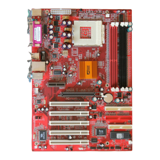
Page 12: Mainboard Components
Mainboard User’s Manual Mainboard Components Use the diagram below to identify the major components on the mainboard. Note: Any jumpers on your mainboard not appearing in the illustration above are for testing only. I/O Ports The illustration below shows a side view of the built-in I/O ports on the mainboard. -
Page 13: Install A Cpu
2: Mainboard Installation Install A CPU This mainboard has a Socket-A supporting AMD K7 processors. To ensure reliability, ensure that your processor has a heatsink/cooling fan assembly. Do not try to install a Socket-370/Socket-7 processor in the Socket-462. A Socket-370/Socket-7 processor such as the PPGA Celeron, FCPGA Pentium-III, Pentium-MMX, or the AMD K5/K6 does not fit in the Socket-462. -
Page 14: Install Memory
Mainboard User’s Manual 4. Match the Pin-1 corners and insert the processor into the socket. No force is required and the processor should drop into place freely. 5. Swing the locking lever down and hook it under the catch on the side of the socket. -
Page 15: Setting Jumper Switches
2: Mainboard Installation 2. Align the memory module with the socket. The DIMM sockets are keyed with notches and the DIMMs are keyed with cutouts so that they can only be installed correctly. 3. Check that the cutouts on the DIMM module edge connector match the notches in the DIMM socket. -
Page 16: Install The Mainboard
Mainboard User’s Manual Install the Mainboard Install the mainboard in a system chassis (case). The board is an ATX size mainboard with a twin-tier of I/O ports. You can install this mainboard in an ATX case. Ensure that your case has an I/O cover plate that matches the ports on this mainboard. -
Page 17: Optional Extension Brackets
2: Mainboard Installation If there are a headphone jack or/and a microphone jack on the front panel, connect the cables to the AUDIO2 header on the mainboard. Here is a list of the header AUDIO2 pin assignment. Signal Signal AUD_MIC AUD_GND AUD_MIC_BIAS AUD_VCC... -
Page 18: Install Other Devices
Mainboard User’s Manual 1. Locate the JUSB1/2/3 header on the mainboard. 2. Plug the bracket cable onto the JUSB1/2/3 header. 3. In the system chassis, remove a slot cover from one of the expansion slots and install the extension bracket in the opening. - Page 19 2: Mainboard Installation Install the device(s) and connect power from the system power supply. Use the cable provided to connect the device(s) to the Primary IDE channel connector IDE1 on the mainboard. If you want to install more IDE devices, you can purchase a second IDE cable and connect one or two devices to the Secondary IDE channel connector IDE2 on the mainboard.
-
Page 20: Expansion Slots
Mainboard User’s Manual Infrared Port You can connect an infrared port to the mainboard. You can purchase this option from third-party vendors. 1. Locate the infrared port IR header on the mainboard. 2. If you are adding an infrared port, connect the ribbon cable from the port to the IR header and then secure the port to an appropriate place in your system chassis. - Page 21 2: Mainboard Installation 3. Insert the expansion card edge connector into the slot and press it firmly down into it so that it is fully inserted. 4. Secure the expansion card bracket to the system chassis using the screw that held the slot cover in place. Note: Please be noted the PCI1 slot (next to the AGP slot) can’t simultaneously work out with USB2.0 controller (VT6202).
- Page 22 Mainboard User’s Manual...
-
Page 23: Chapter 3: Bios Setup Utility
3: BIOS Setup Utility Chapter 3 BIOS Setup Utility Introduction The BIOS Setup Utility records settings and information about your computer such as the date and time, the kind of hardware installed, and various configuration settings. Your computer uses this information to initialize all the components when booting up and functions as the basis for coordination between system components. -
Page 24: Running The Setup Utility
Mainboard User’s Manual Running the Setup Utility Each time your computer starts, before the operating system loads, a message appears on the screen that prompts you to “Hit <DEL> if you want to run SETUP”. When you see this message, press the Delete key and the Main menu page of the Setup Utility appears on your monitor. -
Page 25: Standard Cmos Setup Page
3: BIOS Setup Utility Standard CMOS Setup Page Use this page to set basic information such as the date, the time, the IDE devices, and the diskette drives. If you press the F3 key, the system will automatically detect and configure the hard disks on the IDE channels. -
Page 26: Advanced Setup Page
Mainboard User’s Manual Advanced Setup Page Use this page to set more advanced information about your system. Take some care with this page. Making changes can affect the operation of your computer. AMIBIOS SETUP – ADVANCED SETUP (C) 2000 American Megatrends, Inc. All Rights Reserved Quick Boot Enabled Spread Spectrum... - Page 27 3: BIOS Setup Utility Quick Boot If you enable this item, the system starts up more quickly be elimination some of the power on test routines. Boot Device Use these items to determine the device order the Boot Device computer uses to look for an operating system to Boot Device load at start-up time.
-
Page 28: Power Management Setup Page
Mainboard User’s Manual Clk Gen Spread Use this item to enable the clock to generate spread Spectrum spectrum. DOS Flat Mode This item enables BIOS to enter the DOS protected mode without other software supporting under the DOS operating system. We recommend you leave this item at the default value. -
Page 29: Pci / Plug And Play Setup Page
3: BIOS Setup Utility ACPI Aware O/S Enable this item if you are using an O/S that supports ACPI function such as Windows 98/ME /2000. Power Use this item to select a power management Management scheme. Both APM and ACPI are supported. Suspend Time Out This sets the timeout for Suspend mode in minutes. - Page 30 Mainboard User’s Manual : Help PU/PD/+/- : Modify : Old Values (Shift)F2 : Color : Load Optimal values : Load Best performance values...
-
Page 31: Load Optimal Settings
3: BIOS Setup Utility Plug and Play Enable this item if you are using an O/S that Aware O/S supports Plug and Play such as Windows 95/98/ME. AGP 4X Control This item enables or disables the AGP 4X function. Primary Graphics This item indicates if the primary graphics adapter Adapter uses the PCI or the AGP bus. -
Page 32: Features Setup Page
Mainboard User’s Manual Features Setup Page This page sets some of the parameters for peripheral devices connected to the system. AMIBIOS SETUP – POWER MANAGEMENT SETUP (C) 2000 American Megatrends, Inc. All Rights Reserved OnBoard FDC Enabled OnBoard Serial PortA 3F8h/COM1 OnBoard Serial PortB 2F8h/COM2... - Page 33 3: BIOS Setup Utility OnBoard FDC Use this item to enable or disable the onboard floppy disk drive interface. OnBoard Serial Use these items to enable or disable the onboard PortA/B COM1/2 serial port, and to assign a port address. Serial Port2 Use this item to allocate the resources of the Mode...
-
Page 34: Cpu Pnp Setup Page
Mainboard User’s Manual CPU PnP Setup Page This page lets you manually configure the mainboard for the CPU. The system will automatically detect the kind of CPU that you have installed and make the appropriate adjustments to the items on this page. AMIBIOS SETUP –... -
Page 35: Hardware Monitor Page
3: BIOS Setup Utility Hardware Monitor Page This page sets some of the parameters for the hardware monitoring function of this mainboard. AMIBIOS SETUP – POWER MANAGEMENT SETUP (C) 2000 American Megatrends, Inc. All Rights Reserved --- System Hardware --- Vcore 2.000 V Vcc2.5V... -
Page 36: Exit
Mainboard User’s Manual Change or Remove the Password Highlight this item, press Enter and type in the current password. At the next dialog box, type in the new password, or just press Enter to disable password protection. Exit Highlight this item and press Enter to save the changes that you have made in the Setup Utility configuration and exit the program. - Page 37 3: BIOS Setup Utility...
-
Page 38: Chapter 4: Software & Applications
4: Software & Applications Chapter 4 Software & Applications Introduction This chapter describes the contents of the support CD-ROM that comes with the mainboard package. The support CD-ROM contains all useful software, necessary drivers and utility programs to properly run our products. More program information is available in a README file, located in the same directory as the software. -
Page 39: Installing Support Software
4: Software & Applications Installing Support Software 1.Insert the support CD-ROM disc in the CD-ROM drive. 2.When you insert the CD-ROM disc in the system CD-ROM drive, the CD automatically displays an Auto Setup screen. 3.The screen displays three buttons of Setup, Browse CD and Exit on the right side, and three others Setup, Application and ReadMe at the bottom. - Page 40 Mainboard User’s Manual Auto-Installing under Windows 98/ME/2000/XP If you are under Windows 98/ME/2000/XP, please click the Setup button to run the software auto-installing program while the Auto Setup screen pops out after inserting the support CD-ROM: 1. The installation program loads and displays the following screen.
-
Page 41: Bundled Software Installation
4: Software & Applications Installing under Windows NT or Manual Installation If you are under Windows NT, the auto-installing program doesn’t work out; or you have to do the manual installation, please follow this procedure while the Auto Setup screen pops out after inserting the support CD-ROM: 1.
Need help?
Do you have a question about the M830LU and is the answer not in the manual?
Questions and answers