Table of Contents
Advertisement
This publication, photographs, illustrations and software are under
the protection of international copyright laws and all rights
reserved. It does not allow any reproduction of this manual, content
and any materials contained herein without the written consent of
the authentic manufacturer.
The information in this manual is subject to change without notice.
The manufacturer does neither represent nor warrant the contents
hereof; and specifically disclaims any implied warranties of
merchantability or fitness for any particular purpose. Furthermore,
the manufacturer reserves the right to revise and change this
publication from time to time, without the obligation of notifying
any person of such revision or changes.
Trademarks
IBM, VGA, and PS/2 are registered trademarks of International
Business Machines.
AMD, Duron and Athlon are registered trademarks of Advanced
Micro Devices Inc.
Microsoft, MS-DOS and Windows 98/ME/NT/2000/XP are
registered trademarks of Microsoft Corporation.
PC-cillin is a trademark of Trend Micro Inc.
Award is a trademark of Award Software Inc.
MediaRing Talk is a registered trademark of MediaRing Inc.
3Deep is a registered trademark of E-Color Inc.
It has been acknowledged that all mentioned brands or product
names are trademarks or registered trademarks of their respective
holders.
Copyright © 2003
All Rights Reserved
M811 Series, V3.1
KT266A/May 2003
Advertisement
Table of Contents

Related Manuals for PCchips M811LU


Summary of Contents for PCchips M811LU
- Page 1 This publication, photographs, illustrations and software are under the protection of international copyright laws and all rights reserved. It does not allow any reproduction of this manual, content and any materials contained herein without the written consent of the authentic manufacturer. The information in this manual is subject to change without notice.
- Page 2 Notice: Owing to Microsoft’s certifying schedule is various to every supplier, we might have some drivers not certified yet by Microsoft. Therefore, it might happen under Windows XP that a dialogue box (shown as below) pop out warning you this software has not passed Windows Logo testing to verify its compatibility with Windows XP.
-
Page 3: Table Of Contents
Table of Contents Chapter 1: Introduction..............1 Key Features................2 Package Contents..............5 Static Electricity Precautions...........6 Pre-Installation Inspection............6 Chapter 2: Mainboard Installation...........7 Mainboard Components ............8 I/O Ports...................9 Installing the Processor............10 Installing Memory Modules ..........10 Jumper Settings ..............12 Install The Mainboard ............13 Connecting Optional Devices..........15 Install Other Devices .............17 Expansion Slots ..............19 Chapter 3: Using BIOS..............20... -
Page 5: Chapter 1: Introduction
Chapter 1 Introduction Thank you for choosing this mainboard. It is a high performance and high quality mainboard which is built around the latest and fastest VIA KT266A + VT8235 chipset providing superior performance between the CPU, DRAM, AGP bus, and V-Link bus with pipelined, burst and concurrent operation. -
Page 6: Key Features
Key Features This mainboard has these key features: Processor This mainboard uses an AMD 462-pin Socket A that has the following features: ♦ Supports 100/133 MHz frontside bus (FSB) ♦ Accommodates AMD Athlon/Duron processors Chipset The KT266A Northbridge and VT8235 Southbridge chipsets are based on cost-effective and energy efficient chipset architecture for implementing AGP/PCI desktop personal computer systems with proven reliability and performance. - Page 7 Graphics ♦ The mainboard includes an AGP slot that provides four times the bandwidth of the original AGP specification. AGP technology provides a direct connection between the graphics sub-system and the processor so that the graphics do not have to compete for processor time with other devices on the PCI bus.
- Page 8 ♦ Two PS/2 ports for mouse and keyboard ♦ One serial port ♦ One parallel port ♦ Four USB ports ♦ One LAN port ♦ Audio jacks for microphone, line-in and line-out USB 2.0 ♦ Compliant with Universal Serial Bus Specification Revision 2.0 ♦...
-
Page 9: Package Contents
Dimensions ♦ ATX form factor of 305 x 190mm Package Contents Attention: This mainboard serial has two models, M811LU (LAN, USB2.0) and M811U (USB2.0). Please contact your local supplier for more information about your purchased model. Each model will support different specification listed as below:... -
Page 10: Static Electricity Precautions
Static Electricity Precautions Static electricity could damage components on this mainboard. Take the following precautions while unpacking this mainboard and installing it in a system. 1. Don’t take this mainboard and components out of their original static-proof package until you are ready to install them. 2. -
Page 11: Chapter 2: Mainboard Installation
Chapter 2 Mainboard Installation To install this mainboard in a system, please follow these instructions in this chapter: Identify the mainboard components Install a CPU Install one or more system memory modules Make sure all jumpers and switches are set correctly Install this mainboard in a system chassis (case) Connect any extension brackets or cables to connecting headers on the mainboard... -
Page 12: Mainboard Components
Mainboard Components Identify major components on the mainboard via this diagram underneath. Note: Any jumpers on your mainboard not appearing in this illustration are for testing only. -
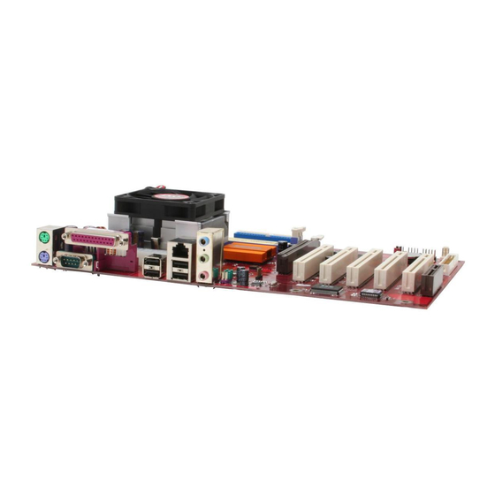
Page 13: I/O Ports
I/O Ports The illustration below shows a side view of the built-in I/O ports on the mainboard. (optional) PS/2 Mouse Use the upper PS/2 port to connect a PS/2 pointing device. PS/2 Keyboard Use the lower PS/2 port to connect a PS/2 keyboard. -
Page 14: Installing The Processor
Installing the Processor This mainboard has a Socket 462 processor socket. When choosing a processor, consider the performance requirements of the system. Performance is based on the processor design, the clock speed and system bus frequency of the processor, and the quantity of internal cache memory and external cache memory. - Page 15 Do not remove any memory module from its antistatic packaging until you are ready to install it on the mainboard. Handle the modules only by their edges. Do not touch the components or metal parts. Always wear a grounding strap when you handle the modules.
-
Page 16: Jumper Settings
Jumper Settings Connecting two pins with a jumper cap is SHORT; removing a jumper cap from these pins, OPEN. JP1: Clear CMOS Jumper Use this jumper to clear the contents of the CMOS memory. You may need to clear the CMOS memory if the settings in the Setup Utility are incorrect and prevent your mainboard from operating. -
Page 17: Install The Mainboard
Install the Mainboard Install the mainboard in a system chassis (case). The board is an ATX size mainboard. You can install this mainboard in an ATX case. Make sure your case has an I/O cover plate matching the ports on this mainboard. Install the mainboard in a case. - Page 18 Front Panel Connector The front panel connector (PANEL1) provides a standard set of switch and LED connectors commonly found on ATX or micro- ATX cases. Refer to the table below for information: PANEL1 Function Function Hard disk LED MSG LED [dual color or (positive) single color (-)] Hard disk active...
-
Page 19: Connecting Optional Devices
Connecting Optional Devices Refer to the following for information on connecting the mainboard’s optional devices: USBCR1 AUDIO1 USB3 AUDIO1: Front Panel Audio header This header allows the user to install auxiliary front-oriented microphone and line-out ports for easier access. Signal Signal AUD_MIC AUD_GND... - Page 20 USB3: Front panel USB connectors The mainboard has four USB ports installed on the rear edge I/O port array. Additionally, some computer cases have USB ports at the front of the case. If you have this kind of case, use auxiliary USB connectors USB3 to connect the front-mounted ports to the mainboard.
-
Page 21: Install Other Devices
Install Other Devices Install and connect any other devices in the system following the steps below. IDE1 IDE2 FDD1 Floppy Disk Drive The mainboard ships with a floppy disk drive cable that can support one or two drives. Drives can be 3.5” or 5.25” wide, with capacities of 360K, 720K, 1.2MB, 1.44MB, or 2.88MB. - Page 22 If you want to install more IDE devices, you can purchase a second IDE cable and connect one or two devices to the Secondary IDE channel connector IDE2 on the mainboard. If you have two devices on the cable, one must be Master and one must be Slave. Internal Sound Connections If you have installed a CD-ROM drive or DVD-ROM drive, you can connect the drive audio cable to the onboard sound system.
-
Page 23: Expansion Slots
Expansion Slots This mainboard has one AGP and five 32-bit PCI slots. AGP1 PCI1 PCI2 PCI3 PCI4 PCI5 Follow the steps below to install the AGP/PCI expansion card. 1. Locate the AGP or PCI slots on the mainboard. 2. Remove the slot cover for this slot from the system chassis. 3. -
Page 24: Chapter 3: Using Bios
Chapter 3 Using BIOS About The Setup Utility The computer uses the latest Award BIOS with support for Windows Plug and Play. The CMOS chip on the mainboard contains the ROM setup instructions for configuring the mainboard BIOS. The BIOS (Basic Input and Output System) Setup Utility displays the system's configuration status and provides you with options to set system parameters. -
Page 25: Starting Setup
• when changing the password or making other changes to the Security Setup Starting Setup The BIOS is immediately activated when you first turn on the computer. The BIOS reads system configuration in CMOS RAM and begins the process of checking out the system and configuring it through the power-on self test (POST). -
Page 26: Standard Cmos Features
BIOS Navigation Keys The BIOS navigation keys are listed below: Function Exits the current menu ←↑↓→ Scrolls through the items on a menu +/–/PU/PD Modifies the selected field's values Saves the current configuration and exits setup Displays a screen that describes all key functions Loads previously saved values to CMOS Loads a minimum configuration for troubleshooting. - Page 27 IDE Devices (None) Your computer has two IDE channels (Primary and Secondary) and each channel can be installed with one or two devices (Master and Slave). Use these items to configure each device on the IDE channel. Here are these sub-items: IDE HDD Auto-Detection Press <Enter>...
-
Page 28: Advanced Bios Setup
Video (EGA/VGA) This item defines the video mode of the system; you must leave this item at the default value. Halt On (All, But keyboard) This item defines the operation of the system POST (Power On Self Test) routine. You can use this item to select which types of errors in the POST are sufficient to halt the system. - Page 29 CPU Internal Cache CPU Internal Cache (Enabled) All processors that can be installed in this mainboard use internal level 1 (L1) cache memory to improve performance. Leave this item at the default value for better performance. External Cache (Enabled) Most processors that can be installed in this system use external level 2 (L2) cache memory to improve performance.
- Page 30 Boot Up Floppy Seek (Enabled) If this item is enabled, it checks the size of the floppy disk drives at start-up time. You don't need to enable this item unless you have a legacy diskette drive with 360K capacity. Boot Up NumLock Status (On) This item defines if the keyboard Num Lock key is active when your system is started.
-
Page 31: Advanced Chipset Setup
OS Select For DRAM > 64 MB (Non-OS2) This item is only required if you have installed more than 64 MB of memory and you are running the OS/2 operating system. Otherwise, leave this item at the default. Video BIOS Shadow (Enabled) This function, when enabled allows VGA BIOS to be copied to the system DRAM for enhanced performance. - Page 32 Current DRAM Frequency This item displays the memory (DRAM) frequency. This is a display-only item. You cannot make changes to this field. DRAM Clock (100 MHz) This item enables you to manually set the DRAM Clock. We recommend that you leave this item at the default value. DRAM Timing (Manual) Set this to the default value to enable the system to automatically set the SDRAM timing by SPD (Serial Presence Detect).
- Page 33 Active to CMD (3T) This item specifies the minimum required delay between activation of different rows. DRAM Burst Length (4) This item describes which burst lengths are supported by the devices on the mainboard. 1 level can provide faster performance but may result in instability whereas 8 level gives the most stable but slowest performance.
- Page 34 CPU & PCI Bus Control This item has several sub-items: PCI 1/2 Master 0 WS Write (Enabled) When enabled, writes to the PCI bus are executed with zero wait states, providing faster data transfer. PCI 1/2 Post Write (Enabled) When enabled, writes from the CPU to PCU bus are buffered, to compensate for the speed differences between the CPU and PCI bus.
-
Page 35: Integrated Peripherals
Integrated Peripherals These options display items that define the operation of peripheral components on the system's input/output ports. Phoenix – AwardBIOS CMOS Setup Utility Integrated Peripherals Item Help USB 2.0 Support [Enabled] OnChip IDE Device [Press Enter] Menu Level OnChip PCI Device [Press Enter] Super I/O Device [Press Enter]... - Page 36 IDE Primary/Secondary Master/Slave UDMA (Auto) Each IDE channel supports a master device and a slave device. This mainboard supports UltraDMA technology, which provides faster access to IDE devices. If you install a device that supports UltraDMA, change the appropriate item on this list to Auto. You may have to install the UltraDMA driver supplied with this mainboard in order to use an UltraDMA device.
- Page 37 ECP Mode Use DMA (3) When the onboard parallel port is set to ECP mode, the parallel port can use DMA 3 or DMA 1. Press <Esc> to return to the Integrated Peripherals screen. Init Display First (PCI Slot) Use this item to specify whether your graphics adapter is installed in one of the PCI slots or is integrated on the mainboard.
-
Page 38: Power Management Setup
Power Management Setup The Power Management Setup Menu option is used to change the values of the chipset registers for system power management. Phoenix – AwardBIOS CMOS Setup Utility Power Management Setup Item Help ACPI function [Enabled] Power Management Option [User Define] Menu Level HDD Power Down... - Page 39 to User Define, you can insert your own timeouts for the power- saving modes. HDD Power Down (Disable) The IDE hard drive will spin down if it is not accessed within a specified length of time. Options are from 1 Min to 15 Min and Disable.
- Page 40 item is set to Delay 4 Sec. then you have to hold the power button down for four seconds to cause a software power down. State After PWR-Fail (Off) This item enables your computer to automatically restart or return to its last operating status after power returns from a power failure. IRQ/Event Activity Detect This item has several sub-items: VGA (Off)
-
Page 41: Pnp/Pci Configurations
PNP/PCI Configurations This section describes configuring the PCI bus system. PCI (Peripheral Component Interconnect) is a system, which allows I/O devices to operate at speeds nearing CPU’s when they communicate with own special components. All the options describes in this section are important and technical and it is strongly recommended that only experienced users should make any changes to the default settings. - Page 42 Resources Controlled By (Auto(ESCD)) You should leave this item at the default Auto(ESCD). Under this setting, the system dynamically allocates resources to plug and play devices as they are required. If you cannot get a legacy ISA (Industry Standard Architecture) expansion card to work properly, you might be able to solve the problem by changing this item to Manual, and then opening up the IRQ Resources and Memory Resources sub-menus.
-
Page 43: Pc Health Status
PC Health Status On mainboards that support hardware monitoring, this item lets you monitor the parameters for critical voltages, critical temperatures, and fan speeds. Phoenix – AwardBIOS CMOS Setup Utility PC Health Status Item Help Target Temperature [Disabled] Shutdown Temperature [Disabled] Menu Level Vcore... -
Page 45: Frequency/Voltage Control
Frequency/Voltage Control This item enables you to set the clock speed and system bus for your system. The clock speed and system bus are determined by the kind of processor you have installed in your system. Phoenix – AwardBIOS CMOS Setup Utility Frequency Control Item Help Auto Detect DIMM/PCI Clk... -
Page 46: Load Optimized Defaults
again. If you only want to install fail-safe defaults for a specific option, select and display that option, and then press <F6>. Load Optimized Defaults This option opens a dialog box that lets you install optimized defaults for all appropriate items in the Setup Utility. Press <Y> and then <Enter>... -
Page 47: Save & Exit Setup Option
Confirm Password: 5. Type the password again and press <Enter>, or press <Enter> if you are deleting a password that is already installed. 6. If you typed the password correctly, the password will be installed. Save & Exit Setup Option Highlight this item and press <Enter>... -
Page 49: Chapter 4: Software & Applications
Chapter 4 Software & Applications Introduction This chapter describes the contents of the support CD-ROM that comes with the mainboard package. The support CD-ROM contains all useful software, necessary drivers and utility programs to properly run our products. More program information is available in a README file, located in the same directory as the software. -
Page 50: Installing Support Software
Installing Support Software 1.Insert the support CD-ROM disc in the CD-ROM drive. 2.When you insert the CD-ROM disc in the system CD-ROM drive, the CD automatically displays an Auto Setup screen. 3.The screen displays three buttons of Setup, Browse CD and Exit on the right side, and three others Setup, Application and ReadMe at the bottom. - Page 51 Auto-Installing under Windows 98/ME/2000/XP If you are under Windows 98/ME/2000/XP, please click the Setup button to run the software auto-installing program while the Auto Setup screen pops out after inserting the support CD-ROM: 1. The installation program loads and displays the following screen.
-
Page 52: Bundled Software Installation
Installing under Windows NT or Manual Installation If you are under Windows NT, the auto-installing program doesn’t work out; or you have to do the manual installation, please follow this procedure while the Auto Setup screen pops out after inserting the support CD-ROM: 1.
Need help?
Do you have a question about the M811LU and is the answer not in the manual?
Questions and answers