Table of Contents
Advertisement
Quick Links
Mainboard User's Manual
This publication, including all photographs, illustrations and
software, is protected under international copyright laws, with all
rights reserved. Neither this manual, nor any of the material
contained herein, may be reproduced without the express written
consent of the manufacturer.
The information in this document is subject to change without
notice. The manufacturer makes no representations or warranties
with respect to the contents hereof and specifically disclaims any
implied warranties of merchantability or fitness for any particular
purpose. Further, the manufacturer reserves the right to revise this
publication and to make changes from time to time in the content
hereof without obligation of the manufacturer to notify any person
of such revision or changes.
Trademarks
IBM, VGA, and PS/2 are registered trademarks of International
Business Machines.
AMD and Athlon are registered trademarks of Advanced Micro
Devices Inc.
Intel, Pentium, Pentium-II, and MMX are registered trademarks of
Intel Corporation.
Microsoft, MS-DOS and Windows 95/98/NT/2000 are registered
trademarks of Microsoft Corporation.
PC-cillin and ChipAwayVirus are trademarks of Trend Micro Inc.
Award is a trademark of Award Software Inc.
A3D is a registered trademark of Aureal Inc.
MediaRing Talk is a registered trademark of MediaRing Inc.
3Deep is a registered trademark of E-Color Inc.
Other names used in this publication may be trademarks and are
acknowledged.
Copyright © 2001
All Rights Reserved
M810 Series, V1.6D
S73X/April 2001
Advertisement
Table of Contents

Subscribe to Our Youtube Channel
Related Manuals for PCchips M810LMR


Summary of Contents for PCchips M810LMR
- Page 1 Mainboard User’s Manual This publication, including all photographs, illustrations and software, is protected under international copyright laws, with all rights reserved. Neither this manual, nor any of the material contained herein, may be reproduced without the express written consent of the manufacturer. The information in this document is subject to change without notice.
- Page 2 AGP VGA cards that we have tested. We will test more AGP VGA cards in the future. Users may get this information from our World Wide Web at www.pcchips.com.tw. Model Chipset Memory Manufacture...
-
Page 3: Table Of Contents
Mainboard User’s Manual Table of Contents Chapter 1: Introduction..............1 Key Features................2 Package Contents..............5 Static Electricity Precautions..........6 Pre-Installation Inspection............6 Chapter 2: Mainboard Installation..........7 Mainboard Components............8 I/O Ports..................9 Install A CPU................9 Install Memory..............11 Setting Jumper Switches............12 Install the Mainboard............13 Optional Extension Brackets..........14 Install Other Devices............15 Expansion Slots..............17 Chapter 3: BIOS Setup Utility............19... - Page 4 Mainboard User’s Manual...
-
Page 5: Chapter 1: Introduction
1: Introduction Chapter 1 Introduction This mainboard has a Socket-462 processor socket for an AMD K7 type CPUs. You can install any one of these processors on the mainboard. The mainboard supports Socket-462 processor front-side bus speeds of 200MHz. This mainboard uses the T-Bird chipset which integrates a 128-bit AGP Graphics Accelerator, and provides a optional 4X AGP slot for highly graphics display, CPU Plug &... -
Page 6: Key Features
Mainboard User’s Manual Key Features The key features of this mainboard include: Socket-462 Processor Support Supports AMD Athlon/Duron processors Supports 200 MHz Front-Side Bus Processors are automatically configured using firmware and a synchronous Host/DRAM Clock Scheme. Memory Support ... - Page 7 1: Introduction Built-in Graphics System Onboard 128-bit 2D/3D 100MHz Host interface AGP Graphics Accelerator Complies with AGP V2.0 Shared memory architecture allows a maximum of 64 MB main memory to act as frame buffer Supports high resolutions up to 1920x1440 Hi-colors, up to 2048x2048 Texture size and Virtual screen up to 4096x4096 ...
- Page 8 Mainboard User’s Manual High Performance provided by 100Mbps clock generator and data recovery circuit for 100Mbps receiver Onboard Flash ROM Automatic CPU and board configuration Supports Plug and Play configuration of peripheral devices and expansion cards Built-in virus protection using Trend’s ChipAwayVirus provides boot process virus protection.
-
Page 9: Package Contents
1: Introduction Package Contents Attention: This mainboard series includes four different models. They are M810LMR (LAN/Modem Ready), M810LR (LAN Ready), M810MR (Modem Ready) and M810 (without LAN & Modem). Please contact your local supplier for your purchase model. Each model will support different specification, list as below:... -
Page 10: Static Electricity Precautions
Mainboard User’s Manual Static Electricity Precautions Components on this mainboard can be damaged by static electricity. Take the following precautions when unpacking the mainboard and installing it in a system. 1. Keep the mainboard and other components in their original static-proof packaging until you are ready to install them. -
Page 11: Chapter 2: Mainboard Installation
2: Mainboard Installation Chapter 2 Mainboard Installation To install this mainboard in a system, follow the procedures in this chapter: Identify the mainboard components Install a CPU Install one or more system memory modules Verify that any jumpers or switches are set correctly ... -
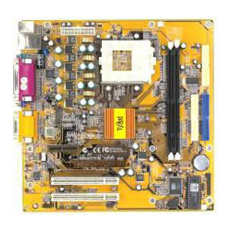
Page 12: Mainboard Components
Mainboard User’s Manual Mainboard Components Use the diagram below to identify the major components on the mainboard. CPU/ Note: Any jumper on your mainboard that do not appear in the illustration above is for testing only. CAUTION: Switching Power Supplier Limitation The switching power supplier MUST support the specification as the following table for AMD K7 CPUs. -
Page 13: I/O Ports
2: Mainboard Installation I/O Ports The illustration below shows a side view of the built-in I/O ports on the mainboard. Install A CPU This mainboard has a Socket-462 CPU socket for AMD K7 processors. To ensure reliability, ensure that your processor has a heatsink/cooling fan assembly. - Page 14 Mainboard User’s Manual Installing a Socket-462 Processor A processor installs into the ZIF (Zero Insertion Force) Socket-462 on the mainboard. 1. Locate the Socket-462 and CPU/PWRFAN. Pull the locking lever out slightly from the socket and raise it to the upright position.
-
Page 15: Install Memory
2: Mainboard Installation Install Memory The mainboard has two DIMM sockets for system memory modules. You must install at least one memory module in order to use the mainboard. DIMM1 DIMM2 For this mainboard, you must use 168-pin, 3.3V unbuffered PC100 or PC133 SDRAM memory modules. -
Page 16: Setting Jumper Switches
Mainboard User’s Manual Setting Jumper Switches Jumpers are sets of pins which can be connected together with jumper caps. The jumper caps change the way the mainboard operates by changing the electronic circuits on the mainboard. If a jumper cap connects two pins, we say the pins are SHORT. If a jumper cap is removed from two pins, the pins are OPEN. -
Page 17: Install The Mainboard
2: Mainboard Installation Install the Mainboard Install the mainboard in a system chassis (case). The board is an Micro ATX size mainboard with a twin-tier of I/O ports. You can install this mainboard in any ATX case. Ensure that your case has an I/O cover plate that matches the ports on this mainboard. -
Page 18: Optional Extension Brackets
Mainboard User’s Manual Optional Extension Brackets For this mainboard, you can also obtain a USB module extension bracket. Install them by following the steps below. Note: All the ribbon cables used on the extension brackets have a red stripe on the Pin-1 side of the cable. Extended USB Module This module bracket has two USB ports for more USB devices (USB port 3-4). -
Page 19: Install Other Devices
2: Mainboard Installation Install Other Devices Install and connect any other devices in the system following the steps below. IDE2 FLOPPY IDE1 Floppy Disk Drive The mainboard ships with a floppy disk drive cable that can support one or two drives. Drives can be 3.5” or 5.25” wide, with capacities of 360K, 720K, 1.2MB, 1.44MB, or 2.88MB. - Page 20 Mainboard User’s Manual If you want to install more IDE devices, you can purchase a second IDE cable and connect one or two devices to the Secondary IDE channel connector IDE2 on the mainboard. If you have two devices on the cable, one must be Master and one must be Slave. Internal Sound Connections If you have installed a CD-ROM drive or DVD-ROM drive, you can connect the drive audio cable to the onboard sound system.
-
Page 21: Expansion Slots
2: Mainboard Installation Expansion Slots This mainboard has two 32-bit PCI expansion slots, one AMR slot and one optional AGP slot. PCI2 AMR1 PCI1 AGP1 Follow the steps below to install a PCI/AMR/AGP expansion card. 1. Locate the AGP, AMR or PCI slots on the mainboard. 2. -
Page 22: Chapter 3: Bios Setup Utility
3: BIOS Setup Utility Chapter 3 BIOS Setup Utility Introduction The BIOS Setup Utility records settings and information about your computer such as the date and time, the kind of hardware installed, and various configuration settings. Your computer uses this information to initialize all the components when booting up and functions as the basis for coordination between system components. -
Page 23: Running The Setup Utility
Mainboard User’s Manual Running the Setup Utility Each time your computer starts, before the operating system loads, a message appears on the screen that prompts you to “Hit <DEL> if you want to run SETUP”. When you see this message, press the Delete key and the Main menu page of the Setup Utility appears on your monitor. -
Page 24: Standard Cmos Setup Page
3: BIOS Setup Utility Standard CMOS Setup Page Use this page to set basic information such as the date, the time, the IDE devices, and the diskette drives. If you press the F3 key, the system will automatically detect and configure the hard disks on the IDE channels. -
Page 25: Advanced Setup Page
Mainboard User’s Manual Advanced Setup Page Use this page to set more advanced information about your system. Take some care with this page. Making changes can affect the operation of your computer. AMIBIOS SETUP – ADVANCED SETUP (C) 2000 American Megatrends, Inc. All Rights Reserved Trend ChipAway Virus Enabled Quick Boot... -
Page 26: Power Management Setup Page
3: BIOS Setup Utility Floppy Drive If you enable this item, your system will check all Seek floppy disk drives at start up. Disable this item unless you are using an old 360KB drive. Password Check If you have entered a password for the system, use this item to determine, if the password is required to enter the Setup Utility (Setup) or required both at start-up and to enter the Setup Utility (Always). - Page 27 Mainboard User’s Manual Standby Time Out This sets the timeout for Standby mode in minutes. If the time selected passes without any system activity, the computer will enter power- saving Standby mode. Suspend Time Out This sets the timeout for Suspend mode in minutes.
-
Page 28: Pci / Plug And Play Setup Page
3: BIOS Setup Utility PCI / Plug and Play Setup Page This page sets some of the parameters for devices installed on the PCI bus and devices that use the system plug and play capability. AMIBIOS SETUP – PCI / PLUG AND PLAY SETUP (C) 2000 American Megatrends, Inc. -
Page 29: Load Best Performance Settings
Mainboard User’s Manual Load Best Performance Settings If you select this item and press Enter a dialog box appears. If you press Y, and then Enter, the Setup Utility loads a set of best- performance default values. These default values are quite demanding and your system might not function properly if you are using slower memory chips or other low-performance components. - Page 30 3: BIOS Setup Utility Parallel Port Mode Use this item to set the parallel port mode. You can select SPP (Standard Parallel Port), ECP (Extended Capabilities Port), EPP (Enhanced Parallel Port), or ECP + EPP. Parallel Port IRQ Use this item to assign either IRQ 5 or 7 to the parallel port.
-
Page 31: Cpu Pnp Setup Page
Mainboard User’s Manual CPU PnP Setup Page This page lets you manually configure the mainboard for the CPU. The system will automatically detect the kind of CPU that you have installed and make the appropriate adjustments to the items on this page. AMIBIOS SETUP –... -
Page 32: Hardware Monitor Page
3: BIOS Setup Utility Hardware Monitor Page This page sets some of the parameters for the hardware monitoring function of this mainboard. AMIBIOS SETUP – HARDWARE MONITOR (C) 2000 American Megatrends, Inc. All Rights Reserved --- Hardware Monitor --- CPU Temperature 30°C/86°F System Temperature CPU Fan Speed... -
Page 33: Exit
Mainboard User’s Manual Change or Remove the Password Highlight this item, press Enter and type in the current password. At the next dialog box, type in the new password, or just press Enter to disable password protection. Exit Highlight this item and press Enter to save the changes that you have made in the Setup Utility configuration and exit the program. -
Page 34: Chapter 4: Software & Applications
4: Software & Applications Chapter 4 Software & Applications Introduction The support software CD-ROM that is included in the mainboard package contains all the drivers and utility programs needed to properly run our products. Below you can find a brief description of each software program, and the location for your mainboard version. - Page 35 Mainboard User’s Manual Note: The correct path name for each software driver is provided, where D: identifies the CD-ROM drive letter – modify if necessary. AGP Driver The AGP Drivers allows the system to properly manage the AGP slot on the mainboard. Find the driver here: ...
-
Page 36: Auto-Installing Under Windows 98
4: Software & Applications BIOS Update Utility The BIOS Update utility allows you to update the BIOS file on the mainboard to a newer version. You can download the latest version of the BIOS setup available for your mainboard from the website. ... - Page 37 Mainboard User’s Manual AutoRun in the context sensitive menu for the CD-ROM drive icon in a file browser window. Installing Software with Auto Setup To install support software for the system board follow this procedure: 1. Click on the Setup button. The install program will load and display the following screen.
- Page 38 4: Software & Applications software you selected to install. When the process is finished, all the support software will be installed and working. There are some utilities that you have to manually install if you need, check to the above section.
Need help?
Do you have a question about the M810LMR and is the answer not in the manual?
Questions and answers