Table of Contents
Advertisement
Quick Links
Mainboard User's Manual
This publication, including all photographs, illustrations and
software, is protected under international copyright laws, with all
rights reserved. Neither this manual, nor any of the material
contained herein, may be reproduced without written consent of
the author.
The information in this document is subject to change without
notice. The manufacturer makes no representations or warranties
with respect to the contents hereof and specifically disclaims any
implied warranties of merchantability or fitness for any particular
purpose. Further, the manufacturer reserves the right to revise this
publication and to make changes from time to time in the content
hereof without obligation of the manufacturer to notify any person
of such revision or changes.
Trademarks
IBM, VGA, and PS/2 are registered trademarks of International
Business Machines.
Intel, Pentium/II/III, Pentium 4, Celeron and MMX are registered
trademarks of Intel Corporation.
Microsoft, MS-DOS and Windows 98/ME/NT/2000/XP are
registered trademarks of Microsoft Corporation.
PC-cillin is a registered trademark of Trend Micro Inc.
AMI is a registered trademark of American Megatrends Inc.
MediaRing Talk is a registered trademark of MediaRing Inc.
3Deep is a registered trademark of E-Color Inc.
SiS is a trademark of Silicon Integrated System Corporation.
Other brands or product names in this manual are trademarks or the
properties of their respective owners and are acknowledged.
Copyright © 2003
All Rights Reserved
M847 Series, V1.5B
S746/February 2003
Advertisement
Table of Contents

Subscribe to Our Youtube Channel
Related Manuals for PCchips M847FLU


Summary of Contents for PCchips M847FLU
- Page 1 Mainboard User’s Manual This publication, including all photographs, illustrations and software, is protected under international copyright laws, with all rights reserved. Neither this manual, nor any of the material contained herein, may be reproduced without written consent of the author. The information in this document is subject to change without notice.
- Page 2 Mainboard User’s Manual Notice: Owing to Microsoft’s certifying schedule is various to every supplier, we might have some drivers not certified yet by Microsoft. Therefore, it might happen under Windows XP that a dialogue box (shown as below) pop out warning you this software has not passed Windows Logo testing to verify its compatibility with Windows XP.
-
Page 3: Table Of Contents
Mainboard User’s Manual Table of Contents Chapter 1: Introduction..............1 Key Features................2 Package Contents..............7 Static Electricity Precautions..........8 Pre-Installation Inspection............8 Chapter 2: Mainboard Installation..........9 Mainboard Components............10 I/O Ports................10 Install A CPU................12 Installing Memory Modules..........13 Setting Jumper Switches............14 Install the Mainboard............15 Optional Extension Brackets..........16 Install Other Devices............18 Expansion Slots ..............20 Chapter 3: BIOS Setup Utility............23... - Page 4 Mainboard User’s Manual...
-
Page 5: Chapter 1: Introduction
1: Introduction Chapter 1 Introduction This mainboard has a Socket-462 processor socket for the AMD K7 type of processors. You can install any of these processors on this mainboard. This mainboard supports front-side bus speed of 333MHz. This mainboard integrates the SiS746 Northbridge along with SiS963 Southbridge chipsets that supports built-in AC97 Codec support 6-channel speak-out, 2 DDR400 (by overclocking) modules up to 2GB system memory. -
Page 6: Key Features
Mainboard User’s Manual Key Features The key features of this mainboard include: Socket-462 Processor Support Supports AMD Athlon XP/Athlon/Duron processors Supports 333 MHz Front-Side Bus Chipset There are SiS746 Northbridge and SiS963 Southbridge in this chipset in accordance with an innovative and scalable architecture with proven reliability and performance. - Page 7 1: Introduction Supports RTC Alarm, Wake On Modem, AC97 Wake-Up and USB Wake-Up Integrated VGA Specification GPU (Graphics Processing Unit) Xabre 200 AGP8X 256-bit GPU clock runs from 200MHz DISPLAY MEMORY Built-in 64MB DDR onboard runs from 400MHz (DDR400) ...
- Page 8 Mainboard User’s Manual RESOLUTION Supports VESA standards super high resolution graphics modes, up to 2048x1536x32 bpp AC97 Audio Codec 6-CH hardware architecture allows multi-channel south bridge to playback 6CH audio Intel AC’97 (REV. 2.2) compatible, meeting Microsoft PC2001 requirements ...
- Page 9 1: Introduction Built-in Ethernet LAN (optional) 10Base-T/100Base-TX Physical Layer Solution Dual Speed – 100/10 Mbps MII Interface to Ethernet Controller/Configuration & Status Auto Negotiation: 10/100, Full/Half Duplex Meet All Applicable IEEE802.3, 10Base-T and 100Base- TX Standards USB 2.0 ...
- Page 10 Mainboard User’s Manual Bundled Software PC-Cillin2002 provides automatic virus protection under Windows 98/ME/NT/2000/XP MediaRing Talk provides PC to PC or PC to Phone internet phone communication 3Deep delivers the precise imagery and displays accurate color in your monitor ...
-
Page 11: Package Contents
1: Introduction Package Contents Attention: This mainboard serial has three models, M847FLU (IEEE1394a, LAN, USB2.0), M847LU(LAN, USB2.0), and M847U(USB2.0). Please contact your local supplier for more information about your purchased model. Each model will support different specification listed as below:... -
Page 12: Static Electricity Precautions
Mainboard User’s Manual Static Electricity Precautions Static electricity could damage components on this mainboard. Take the following precautions while unpacking this mainboard and installing it in a system. 1. Don’t take this mainboard and components out of their original static-proof package until you are ready to install them. 2. -
Page 13: Chapter 2: Mainboard Installation
2: Mainboard Installation Chapter 2 Mainboard Installation To install this mainboard in a system, please follow the instructions in this chapter: Identify the mainboard components Install a CPU Install one or more system memory modules Verify that all jumpers or switches are set correctly ... -
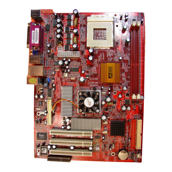
Page 14: Mainboard Components
Mainboard User’s Manual Mainboard Components Identify major components on the mainboard via this diagram underneath. Note: Any jumpers on your mainboard that do not appear in the illustration above are for testing only. I/O Ports The illustration below shows a side view of the built-in I/O ports on the mainboard. - Page 15 2: Mainboard Installation PS/2 Mouse Use the upper PS/2 port to connect a PS/2 pointing device. PS/2 Keyboard Use the lower PS/2 port to connect a PS/2 keyboard. LPT1 Use LPT1 to connect printers or other parallel communications devices. COM1 Use the COM port to connect serial devices such as mice or fax/modems.
-
Page 16: Install A Cpu
Mainboard User’s Manual Install A CPU This mainboard has a Socket-462 that supports AMD K7 processors. To ensure reliability, ensure that your processor has a heatsink/cooling fan assembly. Do not try to install a Socket-370/Socket-7 processor in the Socket-462. A Socket-370/Socket-7 processor such as the PPGA Celeron, FCPGA Pentium-III, Pentium-MMX, or the AMD K5/K6 does not fit in the Socket-462. -
Page 17: Installing Memory Modules
2: Mainboard Installation 4. Match the Pin-1 corner of CPU with the one of socket, and insert the processor into the socket. No force is required and the processor should drop into place freely. 5. Push down the locking lever and hook it under the latch on the edge of the socket. -
Page 18: Setting Jumper Switches
Mainboard User’s Manual 4. Install the DIMM module into the socket and press it firmly down until it is seated correctly. The socket latches are levered upwards and lock the edges of the DIMM. 5.Install any remaining DIMM modules. Setting Jumper Switches Jumpers are sets of pins connected together with jumper caps. -
Page 19: Install The Mainboard
2: Mainboard Installation Install the Mainboard Install the mainboard in a system chassis (case). The board is an ATX size mainboard with a twin-tier of I/O ports. You can install this mainboard in an ATX case. Ensure that your case has an I/O cover plate that matches the ports on this mainboard. -
Page 20: Optional Extension Brackets
Mainboard User’s Manual If there are a headphone jack or/and a microphone jack on the front panel, connect cables to the AUDIO1 header on the mainboard. Here is a list of AUDIO1 header’s pin assignment. Signal Signal AUD_MIC AUD_GND AUD_MIC_BIAS AUD_VCC AUD_FPOUT_R AUD_RET_R... - Page 21 2: Mainboard Installation 3. In the system chassis, remove the blanking plate from the corresponding expansion slot you want to use, and install an extension bracket in there. Secure the extension bracket in the chassis with a screw. Extended IEEE1394 Header (optional) You can obtain one IEEE1394 header JP2.
-
Page 22: Install Other Devices
Mainboard User’s Manual Install Other Devices Install and connect other devices in the system as steps below. FDC1 IDE1 IDE2 Floppy Disk Drive The mainboard ships with a floppy disk drive cable that can support one or two drives. Drives can be 3.5” or 5.25” wide, with capacities of 360K, 720K, 1.2MB, 1.44MB, or 2.88MB. - Page 23 2: Mainboard Installation Internal Sound Connections If you have installed a CD-ROM drive or DVD-ROM drive, you can connect the drive audio cable to the onboard sound system. CD_IN1 CD_IN2 On the mainboard, locate the two 4-pin connectors CD_IN1 and CD_IN2.
-
Page 24: Expansion Slots
Mainboard User’s Manual Onboard LAN LED Connections If you have a set indicator LEDs for the onboard LAN communication, you can connect the LED cable to the header J1. Function Jumper Setting Link LED 1, +2 ACT LED +3, 4 Note: 1. - Page 25 2: Mainboard Installation PCI (Peripheral Components Interconnect) Slots You can install the 32-bit PCI interface expansion cards in the slots. CNR (Communications Networking Riser) Slot The CNR (Communications Networking Riser) slot is an industry standard slot that allows for the installation of a special audio/modem riser card.
- Page 26 Mainboard User’s Manual...
-
Page 27: Chapter 3: Bios Setup Utility
3: BIOS Setup Utility Chapter 3 BIOS Setup Utility Introduction The BIOS Setup Utility records settings and information about your computer such as the date and time, the kind of hardware installed, and various configuration settings. Your computer uses this information to initialize all the components when booting up and functions as the basis for coordination between system components. -
Page 28: Running The Setup Utility
Mainboard User’s Manual Running the Setup Utility Each time your computer starts, before the operating system loads, a message appears on the screen that prompts you to “Hit <DEL> if you want to run SETUP”. When you see this message, press the Delete key and the Main menu page of the Setup Utility appears on your monitor. -
Page 29: Standard Cmos Setup Page
3: BIOS Setup Utility Standard CMOS Setup Page This page sets up basic information such as the date, the time, the IDE devices, and the diskette drives. If you press the F3 key, the system will automatically detect and configure the hard disks on the IDE channels. -
Page 30: Advanced Setup Page
Mainboard User’s Manual Advanced Setup Page This page sets up more advanced information about your system. Take care of this page with more caution. Any changes can affect the operation of your computer. AMIBIOS SETUP – ADVANCED SETUP (C) 2000 American Megatrends, Inc. All Rights Reserved Quick Boot Enabled Boot Device... - Page 31 3: BIOS Setup Utility Quick Boot If you enable this item, the system starts up more quickly be elimination some of the power on test routines. Boot Device Use these items to determine the device Boot Device order the computer uses to look for an Boot Device operating system to load at start-up time.
- Page 32 Mainboard User’s Manual DRAM CAS# Latency This item determines the operation of DRAM memory CAS (column address strobe). It is recommended that you leave this item at the default value. The 3T setting requires faster memory that specifically supports this mode. Timing Setting Mode This item determines the timing setting mode of the memory.
-
Page 33: Power Management Setup Page
3: BIOS Setup Utility Power Management Setup Page This page sets some of the parameters for system power management operation. AMIBIOS SETUP – POWER MANAGEMENT SETUP (C) 2000 American Megatrends, Inc. All Rights Reserved ACPI Aware O/S Power Management Enabled Suspend Time out Disabled Hard Disk Time out... -
Page 34: Pci/Plug And Play Setup Page
Mainboard User’s Manual ACPI Aware O/S Enable this item if you are using an O/S that supports ACPI function such as Windows 98/ME /2000. Power Use this item to select a power management Management scheme. Both APM and ACPI are supported. Suspend Time Out This sets the timeout for Suspend mode in minutes. -
Page 35: Load Optimal Settings
3: BIOS Setup Utility : Load BIOS Defaults : Load Setup Defaults Plug and Play Enable this item if you are using an O/S that Aware O/S supports Plug and Play such as Windows 95/98/ME. Primary Graphics This item indicates if the primary graphics adapter Adapter uses the PCI or the AGP bus. -
Page 36: Features Setup Page
Mainboard User’s Manual Features Setup Page This page sets some of the parameters for peripheral devices connected to the system. AMIBIOS SETUP – FEATURES SETUP (C) 2000 American Megatrends, Inc. All Rights Reserved OnBoard FDC Enabled OnBoard Serial PortA 3F8h/COM1 OnBoard IR Port Disabled OnBoard Parallel Port... - Page 37 3: BIOS Setup Utility Parallel Port DMA Use this item to assign a DMA channel to the parallel port. The options are 0, 1 and 3. Onboard PCI IDE Use this item to enable or disable either or both of the onboard Primary and Secondary IDE channels.
-
Page 38: Cpu Pnp Setup Page
Mainboard User’s Manual CPU PnP Setup Page This page lets you manually configure the mainboard for the CPU. The system will automatically detect the kind of CPU that you have installed and make the appropriate adjustments to the items on this page. AMIBIOS SETUP –... -
Page 39: Hardware Monitor Page
3: BIOS Setup Utility Hardware Monitor Page This page sets some of the parameters for the hardware monitoring function of this mainboard. AMIBIOS SETUP – HARDWARE MONITOR (C) 2000 American Megatrends, Inc. All Rights Reserved *** System Hardware *** CPU Vcore 1.616V Vcc 2.5V 2.496V... -
Page 40: Exit
Mainboard User’s Manual Change or Remove the Password Highlight this item, press Enter and type in the current password. At the next dialog box, type in the new password, or just press Enter to disable password protection. Exit Highlight this item and press Enter to save the changes that you have made in the Setup Utility configuration and exit the program. - Page 41 3: BIOS Setup Utility...
-
Page 42: Chapter 4: Software & Applications
4: Software & Applications Chapter 4 Software & Applications Introduction This chapter describes the contents of the support CD-ROM that comes with the mainboard package. The support CD-ROM contains all useful software, necessary drivers and utility programs to properly run our products. More program information is available in a README file, located in the same directory as the software. -
Page 43: Installing Support Software
4: Software & Applications Installing Support Software 1.Insert the support CD-ROM disc in the CD-ROM drive. 2.When you insert the CD-ROM disc in the system CD-ROM drive, the CD automatically displays an Auto Setup screen. 3.The screen displays three buttons of Setup, Browse CD and Exit on the right side, and three others Setup, Application and ReadMe at the bottom. - Page 44 Mainboard User’s Manual Auto-Installing under Windows 98/ME/2000/XP If you are under Windows 98/ME/2000/XP, please click the Setup button to run the software auto-installing program while the Auto Setup screen pops out after inserting the support CD-ROM: 1. The installation program loads and displays the following screen.
-
Page 45: Bundled Software Installation
4: Software & Applications Installing under Windows NT or Manual Installation If you are under Windows NT, the auto-installing program doesn’t work out; or you have to do the manual installation, please follow this procedure while the Auto Setup screen pops out after inserting the support CD-ROM: 1. - Page 46 Mainboard User’s Manual Rear output adjustable in position, height, and width via C- Media’s user friendly API, capable of offering a freely defined cyberspace to the listener. Xear 3D Mode In Xear 3D Mode, there are Virtual Speaker Shifter/Advance and Earphone Plus Mode options and channel selections.
- Page 47 4: Software & Applications 2-CHANNEL FOUR-CHANNEL SIX-CHANNEL...
- Page 48 Mainboard User’s Manual Earphone Plus Mode While enabling Earphone Plus Mode, it activates the Xear function; moreover, original Front Out and Rear Out positions will be exchanged in Multi-Channel mode. EARPHONE and 2-CHANNEL don’t support Xear function. (Three audio jacks on the screen show these colors: top-- lime, middle-- light blue, bottom-- pink) FOUR-CHANNEL SIX-CHANNEL...
- Page 49 4: Software & Applications Virtual Speaker Shift/Advance Click the Virtual Speaker Shift/Advance button, it provides some 3D Sound Effect and DEMO program for testing.
Need help?
Do you have a question about the M847FLU and is the answer not in the manual?
Questions and answers